I’ve captured some variable stars, both with somebody figuratively holding my hand at almost every step of the way, 22 years ago, at a 2-week summer session at Mount Wilson that I highly recommend, and also with a Seestar S50, after failing a few times.
I was hoping to be able to finally capture an exoplanet transit. I tried in a couple of different ways on the night of January 18-19, but failed. Even so, I count the night as a major success.
It turned out that there were four (yes, 4!) different exoplanets that were supposed to have transits quite visible, during the same night, from my location (Hopewell Observatory in northern Virginia), and I was going to be staying up there all night anyway, with some others.
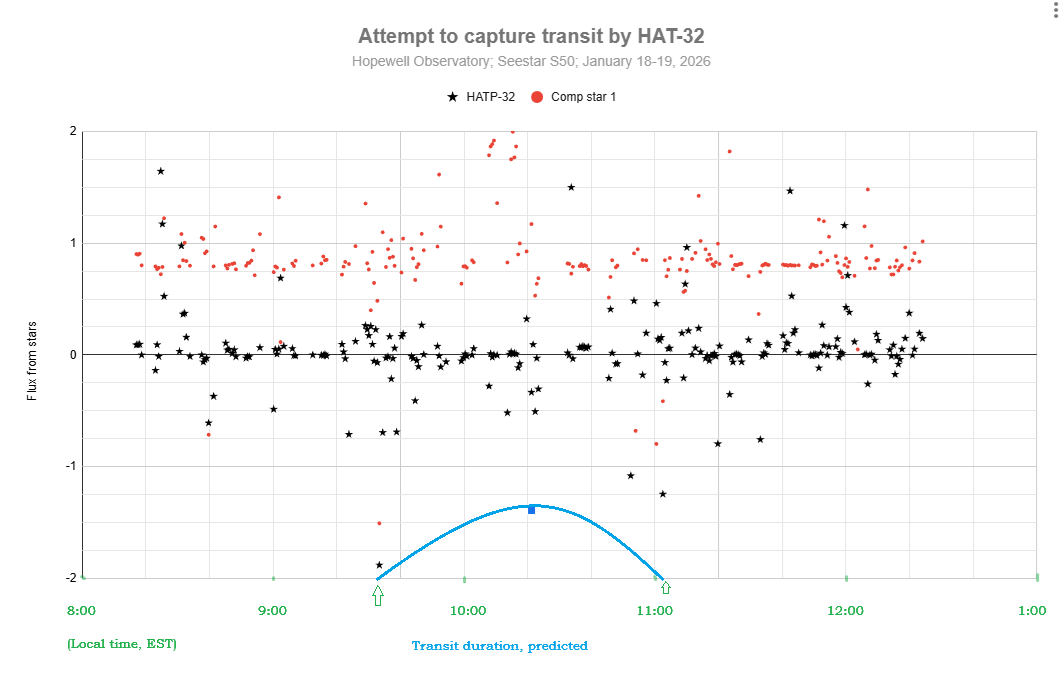
I used the Plan mode of my Seestar to take 30-second exposures of the star that looked like it would be the easiest to capture, namely HAT-P-32, which is in Andromeda at Right Ascension 02h 04m 10.00s and Declination +46° 41` 16.00″, It was supposed to have a depth of transit (or coverage of the star by the planet) of 22.2 parts per thousand, or 2.22%, which I thought sounded like quite a bit.
Unfortunately, it’s not very much at all, at least in terms of star magnitudes!
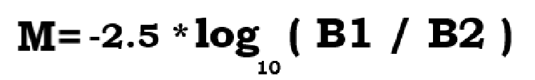
Perhaps you knew (I had forgotten it) the formula for turning brightness changes into magnitude changes.
(M is the magnitude change, B1 is the actual measured flux of photons at time 1 or from star 1, and B2 is the same flux, measured the same way, at time 2 or from star 2.)
You don’t even need to remember what a logarithm is to punch this into your calculator. I found that if you make it so that the ratio of B1 to B2 is one-half, you get a result of 0.75257… and if you try it the other way around, you get the exact same result, with a negative sign in front.
Let’s see: a drop in brightness of 22.2 parts per thousand leaves 977.8 parts per thousand still reaching my telescope. So my B1 needs to be 977.8 and B2 needs to be 1000. Or I could just type -2.5*log(0.9778) and when I do that, I get a drop in magnitude of 0.023, which is not very much at all!
Well, here is my attempt at detecting a transit for HAT-P-32b. I don’t see any sign of a transit. Do you? Part of the problem may have been that my target star was in the trees for part of the time…
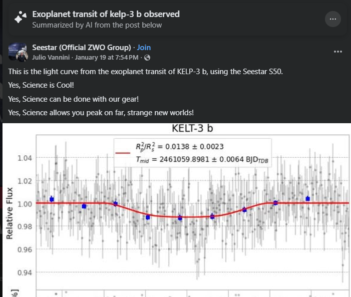
It appears that others have succeeded at this:
I will hope for better weather, better preparation of every step, and fewer tree branches next time!
By the way, here is my workflow. Steps 0 – 2 should be done at home, inside, in comfort, well before leaving for your observing site.
0. You must have both SeeStar and plate solving software (and its databases) operational on your computer. Download and install you have SeeStar, AstroImageJ, Astronometry.net and all of the databases for these accessible on your computer. You can also use ASTAP if you prefer for plate-solving, but AIJ uses Astronometry.net.
Look up which exoplanets are supposed to be visible in your area on the Swarthmore database, for how long, and in what part of the sky. Pick the best ones, with the greatest change in brightness. Print out the data.
2. Connect your Seestar to your tablet or smartphone and create a Plan to image that star for the entire time, with 30 second exposures, no filters, saving every frame. Double-check all your settings! You can do one target after the other, sequentially, but with the current SeeStar software, it doesn’t appear that you can ask it to rotate among several targets for a period of time. If you want to study variable stars, you might find that the Seestar’s pixel wells will get saturated with too many photons, which renders all your time and data is useless. To stop the saturation, set the exposures to as short as possible (10 second exposures), and set the light-pollution filter. If it’s still saturated, you might even need a sub -aperture mask to cut the signal further. You may or may not find that you have to manually change settings at various times during the night; if so, set an alarm for yourself.
3. Later, at the observing site, after sundown: Level your tripod, attach Seestar, turn it on, arrange for a power supply for it, use Bluetooth connect the same tablet or smartphone that you used to make the plan, and tell Seestar to start implementing your Plan. Check the clock and the smart device to make sure Seestar has actually started carrying out the plan. Periodically, re-check to make sure the images look decent. (I have found that Seestar is actually very good at centering your target precisely where you asked it to go to!
4. Let the Seestar do its thing. Check the image that shows up in ‘Star Gazing’ every so often. That window shows you the latest version of the stacked and calibrated image – which you won’t need for attempting to catch an exoplanet transit — not the current sub-exposure.
5. The next morning, in comfort, use a USB-C cable to connect your Seestar to a computer. Use a finder to locate the My Works folder on the Seestar, and find the folder that has all of your subs (frames). They should be in ASIF format. If you like, you can upload them to your computer, or else you can leave them on the Seestar. Take your pick.
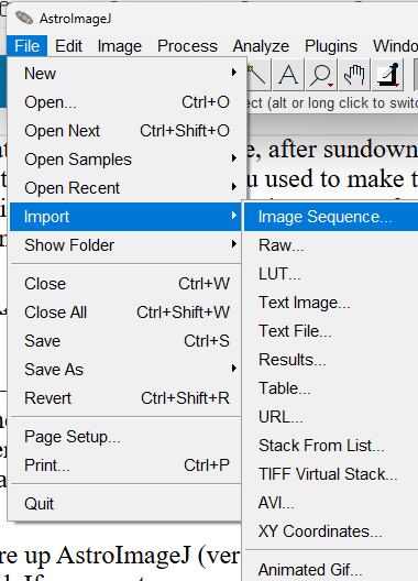
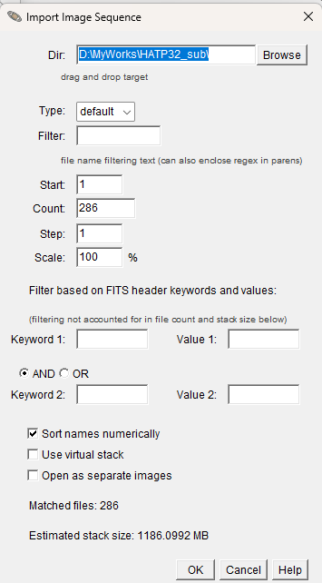
6. Fire up AstroImageJ (version 6) on your computer. Use File/Import Sequence to load that same sequence of subs that you just found. Keep in mind that some parts of the process (especially plate solving) might tie up your computer for a long time, perhaps hours. I would suggest only importing every 10th sub, to begin with, to find out if the whole stack of images is garbage or useful. If desired, you can always import the entire stack later. If I change the Step to 10, it will instead load image #1, then #11, then #21, and so on…
6. Inspect the images, and make a note of the ones you think are garbage. Get rid of those subs.
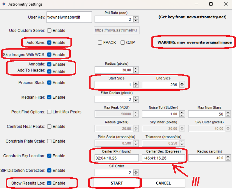
7. Then have AIJ do a plate-solve by chosing WCS (World Coordinate System) then Plate Solve with Astronometry.net (With Options). One of those options should be the coordinates of your star, which you should type in manually. You will need an Astronometry.net user key. You may use mine if you want: tyqwnsiwmabnvdlt. Make sure that Autosave and Skip Images With WCS are Enabled. When you have all that done, click on ‘Start’.
AIJ and Astrometry will then do their best to figure out exactly where the image was in the sky, and will record the RA and Dec of every single object in it and add that to the FITS header. AIJ&A will also indicate which are the cardinal directions. Hopefully, they will be able to solve every image. If Astrometry.net fails, you can try doing the same thing with ASTAP instead, which is insanely fast.
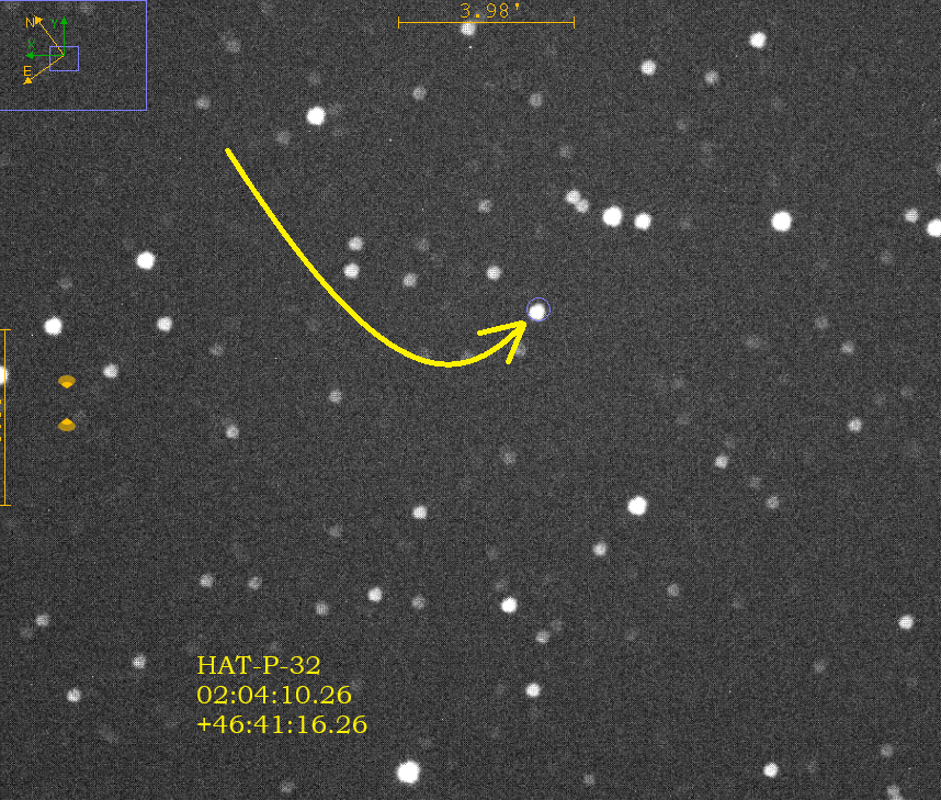
8. Once all of your images have been plate solved, then enlarge one of the images and find your star by checking the coordinates very carefully by moving your mouse around on the image. Since your image has been plate-solved, AIJ now knows exactly how to match the pixels on your screen to the coordinates in the sky, which is extremely impressive! (Try doing that yourself, by eye!) Pay attention to the ‘North” and “East” arrows. North is in the positive declination direction (degrees), and east is the positive right ascension direction (hours). Zoom in to your star, and then do a screen-snip and save it to some other app, and draw arrows showing exactly which star is the one you want, like I did here for my star, HAT-P-32. I also typed in its coordinates. This is for your own reference.
9. The next step is to have the computer compare the brightness of your selected star with a dozen or so comparison stars, and to do so in every frame (or ‘slice’ or ‘sub’), and show you the results in table (spreadsheet) form, and as a graph (chart) of the brightnesses over time of as many of the stars as you like. AIJ does this incredibly well, and incredibly quickly1 You don’t have to go frame by frame, measuring the brightness by eye of each and every single selected star, and noting any changes in brightness, by hand, as was done a century ago or so, in the days of photographic emulsions on thin glass plates. Here is a method for doing it in AIJ:
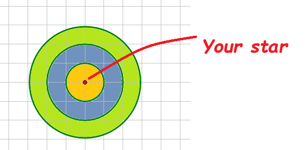
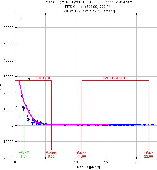
10. So what on earth is it doing, and how does it measure comparative brightness? My understanding is that it draws a three circles of increasing radii around each star, as I show here:
Basically, the software counts all the photons that it captures inside the first ring, which I labeled in yellow. It produces a number: the full width half max. Then it does the same thing for the photons in the outer ring, which it then assumes is the background brightness. I shaded this ring as olive green. It subtracts the FWHM for the yellow ring minus the FWHM of the green ring. It also compares those numbers for all of the comparison stars, and displays all the data in a variety of ways, including a spreadsheet and a graph.
11. Unfortunately, I found that I was unable to get AIJ to make very useful graphs, so I exported the entire spreadsheet into Excel and Google Sheets and made my graphs there.
Here is a link to a much better article on doing much the same thing:
This graph gives me confidence that defocusing will solve my overflow problem. It’s a profile of the number of photons/electrons captured (vertical axis) versus the distance from what I thought was the exact center of the star RR Lyrae aka HD 182989.
(It is amazing how fast the computer works this out! I’m used to my middle school or high school students working things out like this by hand at first — it’s a very slow and tedious process! Let us give a tip of the hat to Williamina Fleming, who was the first person to notice and record that RR Lyrae was a variable star. She did so by examining glass plates on which were little dark spots made by stars’ light striking particles of suspended silver nitrate, without a blink comparator! Wow!)
Notice that there is one
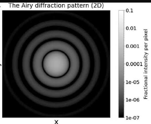
If I defocus the camera a bit, that saturated value would get spread out over an airy disk that might look like this:
We’ve all been brainwashed by years of Star Wars, Star Trek, Marvel Universe, Avatar, etc, to think that space should be teeming with intelligent civilizations, most of them vaguely like ourselves, working with and against each other to carve up the galaxy. As a result, it’s easy to overlook the huge assumptions embedded in your question.
Habitable worlds exist. Do they? It seems overwhelmingly likely, given that there are probably a trillion planets in the Milky Way alone, but for now we don’t know. Perhaps there are many near-miss planets like Venus and Mars, but extremely few true Earth analogs. For instance, life might require a particular rock/ice ratio, a large moon, and a specific style of plate tectonics. That level of specificity seems unlikely to me, but that’s just my random opinion. Until we find another planet with truly Earthlike conditions, we cannot say for sure that this is true.
Alien life exists. Does it? Honestly, we have no idea. There are many strong arguments suggesting that the fundamental biochemistry of self-replication is practically inevitable given the right conditions. But we don’t know how common those conditions are (see above), and even then we don’t know if there is some extremely low-probability gap that hinders the emergence of even simple microbial life.
Intelligent life exists. Does it? This one is a complete unknown. Keep in mind that there was no intelligent, self-aware life on Earth for 99.999% of its existence. Maybe the emergence of intelligence here was a rare fluke, unlikely to be reproduced anywhere else. Rat-level intelligence seems to have existed for at least 200 million years without any indication that higher level intelligence would confer a big evolutionary advantage. (There are all kinds of speculations about why intelligent life could not emerge until now on Earth, but these are just-so stories, trying to paint an explanation on top of a truth that we already know.)
Intelligent species want to “colonize” the galaxy. Do they? Life does have a tendency to explore every available ecological niche, and humans sure do like to spread out. From our example of one Earth, it seems likely that this is a general tendency of life everywhere, but we are doing an awful lot of extrapolating here. Maybe other types of intelligence have other motivations that have nothing to do with expansion.
Intelligent species become technological species. Do they? It’s certainly true for humans, but dolphins have a high level of intelligence and they are not trying to build spaceships. Crows, chimps, and bonobos are also capable of simple tool use, but they don’t appear to have experienced any evolutionary pressure to become true technological species.
Technological species can travel a significant fraction of the speed of light. (I assume you mean something like more than 1% of light speed.) Can they? Extrapolating from human technology, that seems extremely likely. Then again, the fastest spacecraft we have ever built would take about 300,000 years to reach the next star. Nobody is going to be colonizing the galaxy at that rate. You have to accept that speculative but unproven technologies are both feasible and practical for more advanced technological civilizations. Maybe intelligent life is out there, but in isolated pockets.
Intelligent, technological, space-faring species survive for a long time. Do they? Oh boy, we have no idea at all if this is true. Earth is 4.5 billion years old. Life has been around 4 billion years. Land species have been around 400 million years. Rat-level intelligence has maybe been around 200 million years. Our species has been around for about 100 thousand years. We have been capable of spaceflight for less than 100 years. It may seem inconceivable that humans could go extinct—but even if we last another 100,000 years, that may not be nearly enough time to spread across the galaxy, even if we develop the means to do it and maintain the will to do it. If intelligent species typically last less than 100,000 years, thousands of them could have come and gone in our galaxy without us ever knowing.
So there’s not one answer, but a whole set of overlapping possible answers why we don’t see evidence of any alien civilizations around us. And that doesn’t even consider more exotic possibilities, such as the idea that they might be here but just undetectable to us or deliberately hidden from our primitive eyes.
Have you ever visited the golf course at Rock Creek Park in Washington, DC? Despite driving around it thousands of times, I never walked on it until today. Yesterday, I gave insufficiently-informed testimony against a proposed redevelopment of the golf course. Here is what I said, and what I should have included as well.
Hello. My name is Guy Brandenburg. I am a DC native and the current president of National Capital Astronomers, or NCA, a local educational and scientific non-profit astronomy club. I also teach at a school that is directly across 16th Street from the Rock Creek Golf Course!
I and every member of NCA that I’ve spoken to are opposed to installing a brightly-lit night-time golf driving range there.
Right now, the golf course is one of the most nearly pristine areas of the District of Columbia. Installing a illuminated, night-time golf driving range will have a very severe impact on all night-loving creatures in that part of the park. Those creatures include not only insects, birds, four-footed mammals and plants, but also humans nearby.
One special reason for my testimony is that members of my club have been, literally, holding “Exploring The Sky” sessions for the public inside Rock Creek Park, every month except winter, in conjunction with National Park Service Rangers stationed at the Nature Center and Planetarium, for over 75 continuous years, only a short distance from this driving range.
The field where we show planets, stars and galaxies to the public, at no cost, including on Saturday, May 4, two days from now, if the weather is clear, is located just south of the intersection of Military Road and Oregon Avenue – roughly 4200 feet (less than a mile) away from these new lights. Despite today’s testimony by Jamie Herr about the lights, I fear that those new lights will make observing the sky from our site nearly impossible and also affect residents along upper 16th street.
[Addition: My fear was justified. Physics says no such lights exist. Photons go on forever in straight lines unless absorbed, bent, or reflected; they don’t stop after 50 yards! Also, the developers are flat-out lying when they assure the readers that Dark Sky International (DSI) has already approved this lighting plan! I know some of the DSI activists here in DC, and they are hopping mad about this!]
[Addition: I challenge the National Links Trust to show us an example of a night time illuminated golf driving range with this magical 50 yard lighting, anywhere in the world!]
A brightly-lit installation in Rock Creek Park completely contradicts the policy that induced the Park Service to turn off all of the street lights on all of the roads in the park, many years years ago.
I wish more publicity had been given to this night time illumination plan. Previously, I had only heard about the cutting of mature trees. More review of this issue is needed by the local and national DSI.
Yes, I’m biased: I love being outside in a field at night during clear weather. One of my first dates with my wife, over 40 years ago, was a night-time stroll on a moonlit golf course in College Park, serenaded by owls.
Night time is the only time that people can see into the deep universe with their own eyes and see the Milky Way and the stellar furnaces that produced the very molecules that we are all composed of. But wasted, useless lighting at night (or WULAN) – like what I fear this proposed driving range will cause- make it impossible for people to see any of this. As an aside, even if there are habitable planets somewhere, the laws of physics and the vast distances mean there is no way at all to ever reach them. There is no planet B. We do not need to pave over, poison, and light up all of this planet, and especially not this lovely national park!
The current state of this little-used golf course is actually quite lovely. It’s a series of open meadows in the heart of the Nation’s capital, surrounded by large trees. Not being a golfer, the only changes I would recommend would be to remove the invasive alien vines that are smothering so many of those trees.
Let us not bulldoze and light up this lovely set of meadows, and let us review the lighting proposal again.
Guy Brandenburg
[Final addition: The current golf course is an amazing gem, hidden from almost everybody! Until today, I never, ever visited the place, and didn’t know anybody who had. I never even knew where it was until about a week ago, and only today (May 3, 2024) did I at last step on its grounds, though I’ve driven right by it many thousands of times and am a DC native!!!
I am amazed.
The golf course is composed of huge trees that surround amazingly beautiful and almost bucolic meadows! Right in the middle of DC! Much like the Arboretum but wilder, and much nicer than, say, the Franciscan Monastery or Howard Divinity School, or the Old Soldier’s Home!
I was flabbergasted! This golf course incredibly beautiful – in a way that most hyper-manicured golf courses are NOT.
I do think that the landscaping and vegetation need a LOT of serious gardening work, especially since there are lots of really nasty, invasive, alien vines there like English ivy and ‘tear thumb” (persicaria perfoliata). As I strolled and took photos on the ‘back nine’, I saw not a single person for 20 minutes.
As a long-time gardener and one-time farmer, I have a lot of horticultural suggestions for improvements, but the idea of cutting over a thousand big trees, simply because they overshade some of the grass, is obscene! Frankly, that shade makes those lanes much nicer to walk along if it’s hot and sunny — unlike the unshaded National Mall where it gets hot as hell!
But basically, the RCGC s very beautiful as it is, even without any improvement! I even found a pond filled with cattails and bullfrogs, and thickets with lots of wineberries, raspberries and blackberries, blooming right now.
I wish I had known about the place earlier, when I was raising my kids and grandkids! I encourage everyone to go visit, whether you play golf or not! (I do not, but I can see how it might be a great thing to do on this mostly-natural set of meadows, instead of the totally artificial and highly-poisoned typical US golf course.)
Yes, it needs a lot of serious gardening help, but let us not commit obscenities by cutting over a thousand big, beautiful hardwood canopy trees and lighting it all up with a driving range! ]
If each person living in the US, Canada, and Mexico were to travel to the zone of totality on April 8, 2024, it would clearly be an impossible transportation nightmare.
However, if we were somehow able to spread ourselves out evenly, the end result wouldn’t be so bad: only about 4 people per acre! (Or 8 per hectare.)
The eclipse will traverse around 3,000 miles from Mazatlan to Newfoundland, and the zone is on average about 110 miles across. Multiplying those two numbers gives the total area: about 330,000 square miles.
The USA has about 330 million people, Mexico about 120 million, and Canada has a bit under 40 million. Adding those numbers gives about 490,000,000 people. If we divide the total number of people by the total number of square miles, you get about 1500 per square mile.
Now a square mile is defined as 640 acres, so if we divide that 1500 people per square mile by 640 acres per square mile, you get around two and a half people per acre — or roughly five people per hectare…
But of course having everyone spread out evenly like that would be impossible!
Happy New Year! Scientists have proved that folks who celebrate more New Years tend to live longer! If you made it this far, then congratulations! What are your astronomical plans for this new year?
Vera Rubin in the News: You do realize that January 1 is a pretty arbitrary point on our helical journey around the G-class star we call the Sun, as it travels around the super-massive black hole at Sagittarius A*. You may have seen a nifty (but not 100% accurate) animation (e.g. https://www.universetoday.com/107322/is-the-solar-system-really-a-vortex/ ) that shows how the Earth and all the other planets travel on a corkscrew path around the Sun as we all orbit the center of the Milky Way.
Vera Rubin, an early member of NCA, and a long-time DC resident, was featured in the December 2023 issue of Astronomy ( https://www.astronomy.com/science/vera-rubin-found-a-lifetime-of-wonder-in-the-dark-skies/ ) magazine because (as you probably know) she found through careful research that the speeds of stars like ours, as they orbit around their galaxies, don’t make sense if you add up all the known mass and crank out the Newtonian formulas for gravity and their speeds. The stars near the edges of galaxies go just as fast as the ones near the middle, which is NOT true in, say, our solar system, where Mercury travels at 48 km/s, Earth goes 30 km/s, and Neptune’s speed is 5 km/s. So far, nobody has found the missing ‘dark matter’ that would make these speeds work on galactic scales, and no astrophysicist has (to my knowledge) come up with modifications to Newtonian dynamics that both satisfy all the other laws of physics and also solve the problem. We have a profoundly open question, thanks to this pioneering astronomer’s work!
While it is a shame that Vera was never awarded a Nobel prize for her work, NASA and others did rename the Large Synoptic Survey observatory in Chile after her in 2019, and it should be in full operation after we make one more turn around the Sun. (See https://rubinobservatory.org/ and also the December 2023 monthly talk for Northern Virginia Astronomy Club https://www.novac.com/wp/ ).
If you are not a member of the NCA email list-serve, and would like to join it, just send an email to capitalastronomers+subscribe@groups.io . It makes no difference what you put in the subject line or body of the email.
Reminder thatJanuary’s meeting will be strictly virtual. The URL to log in can be found elsewhere in this month’s issue.
You already know that on April 8, a total solar eclipse will make its way across the Pacific Ocean to Mexico, a highly-populated area of the central USA, and eastern Canada.
If you have never seen a total eclipse, then I highly recommend you make plans to do so at least once it your lifetime. It’s the only time you can see the sun’s chromosphere and corona with your naked eyes. It inspires awe in me every time I see it, and I have seen no photo or video that does it justice. Partial eclipses are nice, but nothing beats totality for making you realize that we are only 8 light-minutes away from the incredibly massive thermonuclear reactor that is responsible for our very existence.
If you are planning to go, but don’t already have lodging along the path of totality, a very brief online search suggests that hotels and motels in the zone of totality (e.g. Dallas) seem to have doubled or tripled their rates for the event (understandably). However, there are plenty of other motels that are located within 100 miles of that strip, at much lower prices. Given the great US interstate highway system, it should not be too hard to drive from such a motel to somewhere inside the zone of totality on the morning of the event, even if traffic is heavy.
The lowest probability of clouds along the entire path is at Mazatlàn, but the crime situation today in Mexico is just too scary for me.
My wife and I have arranged for an Airbnb somewhere in Austin and are probably driving from DC to that address, and probably staying put for the event unless a forecast for clouds impels us to drive somewhere else.
I think I’ll bring my own Coronado PST and the 6” scope that I re-made as a travel scope for the 2017 eclipse.
We are putting in an order for hundreds of NCA-branded, safe, solar eyeglasses for NCA members to give away at this and other events. The board has discussed the issue, and my decision as president is that these should be given away, not sold. Why?
Jeff Norman, our assistant secretary-treasurer investigated, and found that while NCA is a non-profit, we would still be required to calculate and collect sales tax and give receipts for each one that we sold; we would need to then pay those funds to the District of Columbia. This is way too much trouble and work for Jim Simpson (our secretary-treasurer) and Jeff, for a relatively small amount of money.
Fewer and fewer people even carry dollar bills or quarters in their pockets or purses, and we definitely don’t want to go through the hassle of doing electronic payments for a dollar or less.
Cash donations from the public might need documentation.
I think the best thing is to use any interaction with the public to recruit any interested person to sign up as a new NCA member at our website and to help out at similar events.
No other astronomy club that I know of is charging the public for these, and we would appear to be less than generous.
If a current NCA member would like to reimburse the club, at roughly the final cost ends up being, for a large quantity of them that you would like to give out at some event, that would be great, but not required.
If you decide to stay in the DMV area for the event, you can help the public enjoy the partial eclipse at the National Air and Space Museum on April 8 with a variety of optical aids, including live feeds from totality. The NCA Hydrogen-alpha double-stack Solar Max telescope will be available for use.
If you are interested, there are several different designs for inexpensive, safe DIY solar viewers. Here is a fairly original one: https://richardsont.people.cofc.edu/safe_solar_folder/the_2-lens_SSV.html . I have made one of these with leftover floorboards, and I have purchased some extra lens sets from Surplus Shed so you can make your own out of wood or cardboard, either at the Chevy Chase Community Center or anywhere you like.
However, it appears that the safe solar viewer in 8a works much better with an achromatic doublet than with the singlet lens in the original design, because the sunspots are not obscured by bluish tinges. I will try that soon.
Please warn people not to look through any scope at the sun without proper solar filters at the front end of the scope!
The sun is putting on quite a show so far this cycle; who knows what will happen in 2024?
John Hornstein reminds us that we still need an NCA member (that is, one of you reading this) to volunteer to be our next vice-president starting in June. This person will be in charge of finding speakers for our monthly meetings, introducing those speakers, and finding candidates for our elected board for the next year. We have a wealth of top-notch astronomical entities in the area (Goddard, Carnegie, STSI, and the Naval Research Lab, to name just four), and many of their staff are more than happy to share their research with us, if we ask them nicely. Plus, we can have remote speakers from all over the world!
Annual dues for regular members are increasing to $15 as of September 2024.
Student dues will stay put for now at $5/year.
In 2025, regular dues will go up again, to $20/year, and student dues will rise to $10/year.
If you want to sign up for a three-year membership, that will also increase next year, to $35, but life memberships will stay at $200.
Exploring the Sky will start up again on April 6, but with a new contact person and planetarium operator, since Ranger Renée Maher is moving to a new position in the NPS .
Renée will be sorely missed. She was the person who came up with the idea of holding planetarium shows and telescope observing on the same evening, which worked out extremely well. She is a great planetarium operator and story teller, and has been great fun to work with as well. She emailed me that she has done many of the steps needed to make sure the joint NCA-NPS-EtS program continues as we did last year, but she doesn’t know who the new contact person will be will be, or even the new supervisor. Her last day at the Rock Creek Nature Center is January 13.
Here is the tentative schedule for these events, as proposed by Jay Miller and me. All dates are on Saturdays, and all times are PM, local time for the DMV region. They are designed so as to not interfere with monthly NCA meetings or national holidays, and to begin somewhere between the end of civil and nautical twilights.
Anybody bringing a telescope is advised to begin setting up earlier than the official starting times, if at all possible.
Month
Day
Sunset
Civil Twilight
Nautical Twilight
Astro- nomical Twilight
Planetarium Show Starts
Exploring the Sky Starts
April
6
7:37
8:04
8:36
9:09
7:30
8:30
May
4
8:15
8:44
9:20
9:58
8:00
9:00
June
1
8:28
8:59
9:38
10:23
8:00
9:00
July
13
8:33
9:04
9:43
10:27
8:00
9:00
August
10
8:08
8:37
9:12
9:49
7:30
8:30
September
7
7:28
7:55
8:27
8:59
7:00
8:00
October
5
6:43
7:10
7:41
8:12
6:30
7:30
November
2
6:05
6:33
7:05
7:36
6:00
7:00
We always need folks who either have scopes or who have information they can share with the public. While Rock Creek Park no longer has the dark skies it did two centuries ago, this event may be the only chance that members of the public will have of seeing the Moon, the planets, and other bright objects with their own eyes, in real time, rather than in a photo.
The planetarium shows occur rain or shine in the Nature Center. Obviously, the telescope observing part of the event will depend on the weather.
I want to thank all of the folks who have brought their scopes to these events this year and during past years. I especially want to thank Jay Miller for organizing the NCA side of this for many years no2.
In the next few months, local counties and cities in the DMV area will host science/STEM fairs. We appear to have sufficient NCA volunteers (thanks!) but we could aways use some more.
When I show people things in the sky with a telescope, I want to help them to realize how lucky we are to live on a nice, warm, wet little planet in a relatively safe part of a medium-large galaxy.
I also want them to realize that if we aren’t careful, we could turn this planet into one of those many varieties of deadly hell that they are viewing in the eyepiece.
We should be very thankful that this planet got formed in a solar system that had sufficient oxygen, silicon, iron, nitrogen, and carbon for life as we know it. We are fortunate that all of those ‘metals’ I just listed (as astronomers call them) got cooked up in cycle after cycle of stars that went boom or whooshed their outer layers into the Milky Way. We are lucky to be alive at the far multicellular side of the timeline of life on Earth*, and that no star has gone supernova in our neighborhood recently or aimed a gamma-ray burst directly at us.
We are exceedingly lucky that a meteorite wiped out the dinosaurs 65 million years and allowed our ancestors, the mammals, to take over. We can rejoice that most of us in the USA can have our physical needs (food, shelter, clean water, clean air, and communication) taken care of by just turning a knob or a key, or pushing a button, instead of hauling the water or firewood on our backs. (There are, obviously, many folks here and abroad who live in tents and who have essentially none of those nice things. We could do something about that, as a society, if we really wanted to.)
I am often asked whether there is life elsewhere. My answer is that I am almost positive that there are lots of planets with some form of life in every single galaxy visible in an amateur telescope. But there is no possible way for us humans to ever visit such a planet. Nor can aliens from any exoplanet ever visit us, whether they be single-celled organisms or something you would see in a Sci-Fi movie.
Yes, it is possible to send a handful of people to Mars, if we are willing to spend enormous sums of money doing so, and if the voyagers are willing to face loss of bone and muscle mass, and the dangers of lethal radiation, meteorites, accidental explosions, and freezing to death. If they do survive the voyage, then by all means, let them pick up some rocks and bring them back for analysis before they die.
But wait: we already have robots that can do that! Plus, robots won’t leave nearly as many germs behind as would a group of human beings. And we already know a lot about how Mars looks, because of all the great photos sent back by ESA, JAXA, NASA and others for some decades now. You can see photos taken by NASA at JMARS, which I highly recommend. (https://jmars.asu.edu/ )
While one can justify sending a few brave folks to Mars for a little while, it is completely insane to think that we can avoid our terrestrial problems by sending large populations there. Mars is often colder than Antarctica, is close to waterless, has poisonous perchlorates in its soil, no vegetation whatsoever, and no atmosphere to speak of. How would millions or billions of exiles from Earth possibly live there? Do you seriously think they can gather enough solar energy to find and melt sufficient water to drink and cook and bathe and grow plants and livestock in the huge, pressurized, aluminum cans they would need to live in? No way.
I wish there was some way to get around the laws of physics, and that we could actually visit other exoplanets. But there isn’t, and we can’t. I’ve seen estimates that accelerating a medium-sized spaceship to a mere 1% of the speed of light would require the entire energy budget of the entire human population of the planet for quite some time. (For example, see https://physics.stackexchange.com/questions/447246/energy-requirements-for-relativistic-acceleration )
Let us assume, for the sake of argument, that you could actually generate enough energy to accelerate that spaceship with nuclear fusion or something else that doesn’t violate the laws of physics as far as we know.
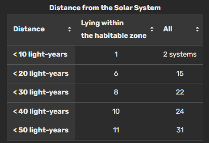
The next problem is the distance. It’s a bit over 4 light years to the nearest known exoplanet in a straight line, (compared with under 2 light-seconds for the Moon or about 35 light minutes for Jupiter). The table below gives the number of planets lying each extra solar system that are thought to be terrestrial (as opposed to gas giants) and to be within their stars’ habitable zones. Nobody knows if there is any life on any of those planets right not, but it is possible that astronomers may one day figure out a very effective way to test for extra-solar life. Let us suppose that a few of the ones in this list do have breathable atmospheres and are neither too cold nor too hot, have a fair amount of liquid water, and are protected from nasty radiation by magnetic fields and belts.
Unfortunately, a one-way trip to Proxima or Alpha Centauri for any possible spaceship, at one percent of the speed of light, (3,000 km per second), in a straight line, and pretending that you don’t need years and years to both accelerate and decelerate, would take over four centuries. And that’s for the very closest one! All the other planetary systems are many multiples of that distance! See this or this table:
Our fastest spacecraft so far, the Parker Solar Probe, reaches the insanely fast speed of 190 km/sec, but that’s still fifteen times slower than my hypothetical 1% of c. At the speed of Parker, it would take around six thousand years to reach the Proxima Cen planetary system! If all goes well!
Do you seriously think that a score or so generations of humans would all agree, century after century, that they, and their descendants — born and raised in a big metal box rushing through space — for the entire 400 years, would consent to live in a large metal box with no gravity to speak of, subject to who knows how many blasts of gamma rays, x-rays, and super-high-energy cosmic particles? What are the chances that each single generation would agree to stay the course and that not a single meteorite going the other direction, over a course of four centuries, would happen to smash into the space ship and instantly disable all the life support systems and kill all the passengers, quickly or slowly?
And how do you keep alive all the animals we would need to feed us upon arrival? I guess you compost all the poop from all the cattle, chickens, and so on. But do you also bring zillions of insects and tons of plant seeds as well, knowing full well that if you do so, then you lose the vast majority of the information you could have learned about an actual, functioning, extra-solar ecosystem like nothing we can possibly imagine.
The argument is made that perhaps the travelers would be put into suspended life. If that were possible, and nothing went wrong, upon arrival, they could take a triumphant group selfie and put it into a radio message back to Earth saying, “Hi, we made it, wish you were here…” That reply will of course take four years to reach Earth. Would people back on Earth still remember the handful of people who began the trip out, made over four centuries earlier? What will the humans back on earth remember about the absolutely prodigious effort expense that their ancestors had made to build and power that rocket, 20 generations or so earlier?
Let us suppose they have the tremendous luck to find, after 4 to 10 centuries of travel, a nice warm exoplanet with water, oxygen-producing life, and air that we can breathe.
Unfortunately, there is an overwhelming chance that there would be no humanoids or any other Sci-Fi characters. The chances are that creatures that look like insects, crustaceans, fish and salamanders are the most highly-organized life forms – at best; after all, for most of the existence of life on earth, it was single-celled organisms! Our travelers would have to have to build an entire urban and agricultural infrastructure *from scratch*, with no help. They could only do that if the plants and animals they brought from Earth are able to flourish.
The return trip, if desired, would of course take another four or more centuries, if the handful of travelers can find a proper power source and if they can figure out how to create, completely from scratch, an entire agricultural and industrial instructure. They would have to figure out where the natural resources of that planet (wood? minerals? energy sources?) are located, and how they can make use of them, to build something like the incredibly precise absolutely enormous rocket-building industries we have here, on a hypothetical planet that has never even had any mammals living on it.
If these voyagers should run into any technical problem while doing trying to build a modern civilization from nothing, fat chance of getting a prompt reply from Earth, since the question would take years to reach its home base back here!
Yes, the very closest exoplanets are a mere 4 LY away, but the others are all much, much farther away, so one-way trips for ones within 10 parsecs, i.e., in our tiny corner of our galaxy, at one percent of the speed of light, would require a thousand to three thousand years to reach. Each way.
Forget it. Just send a radio message, and see if we get a reply. Oh, wait – we’ve been doing that for several decades so far. No reply so far.
Speaking of radio – it’s only 120 years since Marconi first sent a very crude radio message from a ship to a station on land, and now we routinely use enormous parts of the entire electromagnetic spectrum for all sorts of private and public purposes, including sending messages like this one. Astronomers are able to gather amazing amounts of information via the longest radio waves to the very shortest gamma rays and make all sorts of inferences about worlds we have never seen at optical wavelengths. In addition, we have begun detecting gravity waves from extremely distant and powerful events with devices whose accuracy is quite literally unbelievable.
There is no planet B. We must, absolutely must, take care of this one, lest we turn into one of those freezing or burning variations of hell that we see through our eyepieces. Think I’m being alarmist? We now know this nice little planet Earth is more fragile than we once believed. It has been discovered that life was almost completely wiped out on this planet several times. The Chixculub impact I mentioned earlier, the Permian extinction and Snowball Earth are just three such events.
More recently, folks thought it was impossible for people to cause the extinction or near-extinction of the unbelievably huge flocks and herds and schools that once roamed the earth: passenger pigeons, buffaloes, cod, salmon, redwoods, elms, chestnuts, elephants, rhinos, tropical birds, rainforests, and so on, but we did, and continue to do so. The quantities of insects measured at site after site around the world have plummeted by 30 to 70% and more, over just a few decades, and so have the numbers of migratory birds observed on radar feeds. Light pollution, the bane of us amateur and professional astronomers, seems to be partly responsible for both the insect and bird population declines. The rise in the levels of atmospheric carbon dioxide and global temperatures are very scary.
In addition, we are dumping incredible amounts of plastic into the oceans, and rising water temperatures are causing coral reefs around the world to bleach themselves and die, while melting glaciers are causing average sea levels rise and threaten more and more low-lying cities.
What’s more, only a very tiny fraction of our planet’s mass is even habitable by humans: the deepest mine only goes down a few miles, and people die of altitude sickness when they climb just a few miles above sea level. Most of the planet is covered by ocean, deserts, and ice cap. By volume, the livable part of this planet is infinitesimal, and the temperatures on it are rising at an alarming rate.
Will we be able to curb the burning and leaking of fossil fuels sufficiently so as to turn around the parts of global warming caused by increases in carbon dioxide and methane? I am not optimistic, given that the main emitters have kept essentially none of the promises that they have been making to those various international gatherings on climate, and graphs like this one, taken from: https://ourworldindata.org/fossil-fuels
I have been wondering whether we may need to reduce temperatures more directly, by putting enough sulfur compounds into the stratosphere. We have excellent evidence that very violent volcanic eruptions have the power to lower global temperatures with the sulfates they put into the stratosphere. It would not be great for ground-based astronomy if such compounds were artificially lofted high into the atmosphere to lower global temperatures, and we won’t know for sure exactly which areas of the planet would benefit and which would be harmed, but at least it’s an experiment that can be stopped pretty easily, since the high-altitude sulfates would dissipate in a few years. High-altitude sulfur compounds do not seem to cause the obvious harm that SO2 does at the typical altitude of a terrestrial coal-burning power plant.
Adding iron to the oceans to increase the growth of phytoplankton, which then consumes CO2, dies, and settles to the bottom of the ocean, has been tried a number of times, but doesn’t seem to have a very large effect.
I agree that large-scale injection of sulfates into the stratosphere is scary. I also agree that there is a whole lot of unknown unknowns out there and inside of us, and we are being very short-sighted, as usual.
We have mapped the far side of the moon better than we have mapped the floors of Earth’s oceans – yet permits are being filed right now to begin deep-ocean dredging for manganese nodules, which will enrich some folks greatly. Unfortunately, that dredging is bound to utterly destroy those slow-growing ecosystems, before we even know what’s down there in the first place!
We continue to dump unbelievable amounts of plain old trash, fish nets, fishing lines, live ammunition, modern warships and hazardous chemicals into the oceans.
While the waters and atmosphere of the USA are much, much cleaner now than they were when I was a kid in the 50s and 60s, places like Delhi or Beijing are so polluted that folks can barely see the sun on a clear day.
If dark matter and dark energy really do exist, that means that scientists have absolutely no idea what 96% of the universe is made of!
If dark matter and dark energy don’t exist, then that means that astrophysicists don’t understand long-distance gravity and physics nearly as well as they thought. The late Vera Rubin (a past NCA member who should have won a Nobel for her careful measurements of the rotational measurements of galaxies that led to the Dark Matter hypothesis) once told me when we were co-chaperoning a field trip to the Smithsonian for the Carnegie Institution for Science’s Saturday program for middle-schoolers, that she thought that the entire question is perfectly open. I think she’s still correct.
If the Big Bang is real, then how come the Webb is seeing fully-formed galaxies as far back in time as it can see?
Do the alternative theories to the Big Bang (eg, Burbridge’s hypothesis that matter is being created in the centers of active galactic nuclei) make any sense?
But — does anybody have better solutions?
Can we engineer our way out of the mess we are making on this planet – the only home that humans will ever have?
There is cause for optimism:
Our NCA speaker this month, Deborah Shapley, will tell how, almost exactly a century ago, astronomers finally figured out that the Milky Way was just one of many billions of other galaxies. Since that time, the amount of astronomical information gathered has been staggering, as has the efficacy of the instruments!
After scientists figured out what was causing the ozone hole, every single agency and government in the entire world passed and enforced regulations that banned those chlorofluorocarbons that were used in almost everything from air conditioners to hair spray. Since that time, there has been almost complete compliance and agreement, and the ozone hole continues to shrink, as you can see here.
I have vivid memories about how smoggy and stinky the air used to be on a typical summer day in almost any American city of my youth. A fat-rendering plant right here in Georgetown (DC) stank worse than a hundred skunks, and is now gone. I know a paper mill in West Virginia whose fumes had long killed almost all the vegetation downwind of the factory. Nearby, acid drainage from an abandoned coal mine turned a stream so acidic that the rocks (and water) were amazing shades of orange, reds, and yellow. The rivers of this national often flowed with raw sewage, trash, and mine waste. Some, like the Cuyahoga, even caught fire, repeatedly (see https://www.smithsonianmag.com/history/cuyahoga-river-caught-fire-least-dozen-times-no-one-cared-until-1969-180972444/ ). The passage and actual enforcement of the Clean Air and the Clean Water Acts have cleaned up the air and water in this country to an amazing degree in my lifetime (I’m over 70). The cleanup of the Potomac and Anacostia Rivers in that period has also been tremendous. However, my friends who grew up in India and China tell me that the air and water pollution over there is worse than I can possibly imagine and is not improving at all.
When I was young, it appeared that nearly every adult I knew chain-smoked cigarettes and drank a lot of alcohol, and the bars, restaurants, dormitories, private houses, classrooms, buses and airplanes everywhere were filled with tobacco smoke. Despite the lies and obfuscation of the tobacco industry, not only legislation but also public opinion is such that today, I seldom encounter the nasty smell of tobacco smoke anywhere, even on people’s clothing on the bus or subway, and the number of drunk-driving fatalities is way down as well.
During my youth, the various nuclear powers exploded literally hundreds of nuclear weapons in the open air and underwater, spewing Strontium-90 and other radionucleides into things like cow or human milk, and doing untold destruction to the oceans nearby. While the number of world-wide nuclear explosions per year has dropped tremendously since then, they still continue, and may start up again on a larger scale.
Some noteworthy experiments re stopping global warming are listed in this month’s National Geographic. One of them, which has promise but also obvious drawbacks, involves dumping large quantities of finely ground-up alkaline rocks and minerals like olivine counteract the increasing acidification of the seas being caused by the absorption of so much carbon dioxide. Will these experiments work? I don’t know.
But let us not turn this planet – the only home we will ever know – into one of the barren, freezing or boiling versions of hell we see in the eyepieces of a telescope.
I have raised pigs, and I noticed that they never foul their own beds, if they are given any room to move around. Let’s be better than pigs and stop trying to extract riches in the short run while destroying the lovely planet we all love in the long run!
Heaven is not somewhere else.
It’s right here, if we can keep it that way and fix the damage we have done.
* For five-sixths of the roughly 3.7-billion-year time line of life on earth, all living things were single-celled microbes (or microbes living together in colonies). We mammals have only been important for the last 1.7% of that time, (ie since the dinosaurs died out 66 million years ago), the first known writing system was invented a few millennia ago, and Marconi only sent the first ship-to-shore radio message 130 years ago, which is an infinitesimally small fraction of 3.7 billion. Home radios only became popular 100 years ago.
Assuming that planets and stars are created at random times in the history of the universe, and assuming that a certain amount of enrichment of the interstellar medium by many generations of dead stars is necessary before life can begin at all, then it looks to me like the odds are not at all good for intelligent life of any sort to exist right now on any random planet we may study. And, unfortunately, if they do exist, we will never meet them. If there is an incredibly advanced civilization somewhere within 100 light years that can actually detect those first radio signals, then they just received our first messages. If they do respond, we won’t get the answer for another century or two!
For example, take a look at this time line of life on earth at a linear scale. If a hypothetical space traveler should somehow arrive on the 3rd rock from our Sun at a random moment in time over the past 4.5 billion years, then that’s like tossing a dart at this graph while blindfolded, and seeing where it lands. Notice the kind of organisms dominating during most of the past 4 billion years! The chances that they would happen to arrive here in the past few centuries or so, when we humans began to really understand science, are vanishingly small!
My original title began with “Space Travel is Impossible” — which is obviously false, because it is an incontrovertible fact of history that a handful of American astronauts, at enormous expense, did in fact land on the Moon and return. I remember the event well; I was working in a factory in Waltham, Mass that summer as part of the SDS Summer Work-In.
I should have written, “Space Travel to Exoplanets Is Impossible”.
But you could make the case that traveling to the Moon is barely even space travel! The distance to the moon is less than the total mileage on my last two automobiles (a Subaru Forester and a Toyota Prius) added together. Or, at the speed of light, the Moon is about 1.5 light-seconds away, the Sun about 8 light-minutes, Jupiter 34 light-minutes, and Saturn is about 85 light minutes this month. But the very nearest star-planet system to us is over four YEARS away, and the distances to the vast majority of exoplanets are measured in light-decades, light-centuries, or light-millennia.
I remember the Space Race! Both the USA and the Soviets poured incredible sums of cash, labor, raw materials, and brain power into that race, while, frankly, millions of people around the world starved or were killed in proxy wars between those two powers, representing two ideological and political opposing blocks. The incredibly expensive and dangerous race to win global prestige by being the first power bloc to reach the various goals has, so far, at its apogee, carted a handful of men to the near side of our Moon, less than two light-seconds away! And some people think we can easily travel to exoplanets that are light-decades or light-centuries away!
There is a pretty well-known paradox which goes something like this:
You hear that the Smith and Jones families each have two children.
You are told that the older Smith child is a girl, and that at least one of the Jones children is a girl.
Assuming that boys and girls are equally likely to be born (I know this is not quite true, but let’s pretend) in any given pregnancy, what are the chances that the Smiths have two girls? How about the Joneses?
Most people would say that those probabilities are equal: 50% in both cases.
But they are not. In fact, it is much less likely that the Joneses have two daughters!
Here is why:
In any family with two children, there is an older sibling and a younger one.
In the Smith family, you know that the older child is a girl, but you know nothing about their younger child, so the younger one is equally likely to be male or female. So the chances that the Smiths have two daughters is indeed 1/2, or 50%.
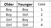
In the Jones family, all we know is that there is at least one girl. Let’s look at a diagram that shows all of the equally-likely possibilities in any family with two children:
With the Smith family, we can rule out cases 1 and 2, leaving us cases 3 and 4.
However, with the Jones family, we can only rule out case number 1. Cases 2, 3, and 4 — which are all equally likely — are all possible outcomes for the Joneses. Notice that only in case number 4 do the Jones have two daughters. So with the Joneses, the chances that there are two daughters is only 1 in 3, or 33.3%.
Fascinating article about how the origins of the telescope are not quite so clear after all. (Pun intended!)
(EDIT: Roger wanted me to emphasize that he doesn’t think he has the final word on this history. Later, I’m going to try to make his graphics more visible, too. Looks like WordPress has changed how you add photos again!)
More on the Origins of the “Telescope.” LONG! From: Roger Ceragioli Date: Mon, 25 Jul 2022 21:30:48 EDT
Greetings again. The Galilean telescope is a peculiar beast optically. Part of the reason it was the first form of telescope was that it gave an erect image, using only two lenses. But because there is a particular third optical element (the human eye) involved, we need to consider the total sytem (convex objective, concave eyepiece, human eye) to understand what may have happened in 1608 as well as in the decades prior.
And so in this email, I want to review some aspects of this “bionic” system. Part of what has, in my opinion, afflicted the debate over the origins of the telescope is lack of attention to the nature of this total bionic system.
Now, it is, of course, hardly conceivable that if the first eyeglasses came into use around 1295 AD, using convex lenses to treat long-sightedness (presbyopia), and concave lenses came into use around 1450 to treat myopia, for 150 years no one bothered to experiment with placing different types of lenses together to find out what would happen. As I mentioned previously, we read in Fracastoro’s book, Homocentrica (a book on planetary theory) about the marvelous effects of putting one convex lens on top of another. Apparently this means directly on top of one another, and not at a distance. Still it shows that people were putting lenses together in the 16th c.
Giovanni Battista della Porta in 1589 mentions combining a convex with a concave (ie. the essence of an early telescope), and that if you know how to do it right, both nearsighted and farsighted people can see clearly. So I would propose, not that he “invented” the telescope, but that he took a step forward and invented a kind of variable focus low power two-lens eyeglass system. It could have been constructed as follows:
Pay no attention to the title of the slide, when it says “Galilean-Type Refractor.” Instead, notice the magnification: 1.25x (a VERY low power), and how the device is constructed. You have on left a 4-diopter (10-inch focus) convex lens, good for old people to do close-up work. And on left a 5-diopter concave, good for strongly myopic people. You do the viewing from right to left through the eyepiece, placing your eye’s pupil as shown.
Now, part of the reason why eyeglass lenses can be optically quite terrible and work just fine, is that in daylight the eye’s pupil closes down to about 2 or 3 mm in diameter. In the dark at night it opens to 5, 6, 7 or even 8 mm, depending on age, to let in more light. The above diagram assumes 2 mm. The blue, green, and red lines passing from left to right represent NOT colors of light, but different ray bundles coming from differing directions out of the graphic on left. I.e. different field positions. Blue is on-axis, green is 2 degrees off-axis, and red is 4 degrees off-axis. The bundles all converge on the eye’s biological pupil and are focused onto the retina.
What’s important here is that in this sytem, the eye’s pupil becomes the delimiting factor in determining how much light enters the eye from each object point. By one definition of magnification,
Magnification = Diameter of Entering Bundles/Diameter of Exiting Bundles in a telescope.
By measuring the bundle diameters we derive the magnification. So, for example, if you have a 200 mm telescope mirror, then the entering bundle is 200 mm in diameter. And if the exiting bundle is only 1 mm in diameter after it comes out of your eyepiece, then we can say that your telescope’s magnification is 200x. In the diagram above, if the magnification is 1.25x and the bundles of rays passing out of this “telescope” and into your eye are each 2 mm in diameter, then by the equation the bundles entering the objective must by 2 x 1.25 = 2.5 mm.
So in the above system, the objective lens doesn’t need to be any better than a common eyeglass lens for the viewer to find the (barely magnified) scene perfectly sharp. It would, therefore, have been easy for Della Porta to make the above device and have it work just as he says. In 1609, when asked, he sent the following rough sketch:
Crude, but it sure looks like a telescope. The “c” tube “trombones” in and out to focus. By this stage 20 years later, Porta was sneering at the device and calling it “crap.” Crap in the sense that it was amusing, but had little effect on “making things nearer.” With my 1.25x version above, the length of the device would be about 100 mm.
The image quality (assuming decent glass) would be perfect all over the field:
Here the colored dots do represent colors of light. The black circles represent the size of the Airy disks. Since the dots for the three sample colors (486, 546, and 656 nm representing the visual spectrum) all fall well within the black circles, we can surmise that a viewer using the system will see everything sharp. The device is only of interest in showing the basic geometry of a Galilean-style refractor, and in that it can focus to varying distances, from infinity to about 2 meters. Anyone can use it, since like a telescope no matter what the state of your eyes (nearsighted or farsighted) you can refocus. But the magnification is hardly noticeable.
Now, if you try to increase the magnification, then the difficulties arise. Let’s say we replace the eyepiece with one that magnifies to 6x:
Here I have stretched the drawing vertically by 5x versus reality to make the paths of the rays for different field positions clearer. The first thing that’s happened is that because of the 6x magnification, now the entering bundles are 2 x 6 = 12 mm in diameter! For each field position, the entering rays cover much more of the objective lenses surface now, just as in a real telescope. But, indeed, this IS now a real telescope!
The result is that any appreciable defects in the objective lens WILL degrade the image. If the glass is of low quality in transmission, or if the lens surfaces are not very spherical, they will blur the images, just as the objective in your childhood “Trashco” telescope used to do. It is these problems that Rolf Willach rightly pointed to in his book, The Long Route to the Invention of the Telescope. But there are still more that he did not discuss.
Because in this type of optical system the “pupil” (ie. where all the ray bundles intersect) as at the eye, and there is a lot of refraction far away at the objective lens, you will inevitably get “lateral color” in the images:
Here we have a spot diagram for the 6x system. On-axis we’re ok. But off-axis at 0.125 and 0.25 degree (the true field of view is now much smaller than before), the red, green and blue bundles are decentered from one another. That means that stars will be seen stretched and smeared, ie. very unsharp. Also, on-axis we now see longitudinal chromatic aberration, although not bad. This system won’t work well as a telescope, because most of the field of view will be smeared. It is this effect (as well as any smearing from surface figure error or glass inhomogeneity) that Lipperhey needed to correct.
He did so, it appears to me, probably by imposing a diaphragm on his objective lens. We don’t know this for certain, but it is very likely, as Willach first suggested. Now, the important part to understand is that if the objective diaphragm makes the bundles of rays exiting the eyepiece smaller than the eye’s own pupil, then what Lipperhey really did was to transfer the pupil of the bionic system from the human eye to the objective lens (where it should be for a telescope). This transference instantly sharpens images in the outer field:
The system layout and raypaths now look like so:
The entering bundles all intersect at the objective and diverge where the eye pupil goes. So we get much sharper images, with much reduced chromatic effects, but at the cost of a narrow, very narrow field of view. Galilean telescopes are infamous for their narrow fields of view. You have to “scrunch” your eyeball up against the eyepiece glass and move it side to side to see as much field as possible. This is inevitable given the optics. And it all gets worse in general as the magnification increases.
If you want to reach even 20x or 30x, it’s necessary to make the telescope longer and longer, to mitigate the chromatic effects. My 6x system above is only about 400 mm long, similar to terrestrial telescopes seen in early images. But for an astronomical telescope, magnifying 20 or 30x, you might need triple or quadruple of that. With triple or quadruple of the objective size. That is 24 or 32 mm. Galileo’s famous 1610 telescope with which he found Jupiter’s largerst moons, seems to have had an aperture of 38 mm. It required a mounting (as Galileo advised) to hold it steady.
To conclude, we have a number of other people aside from Lipperhey who claimed to have used a device similar to his before him. Certainly, Della Porta did in 1589. And perhaps also, Jacob Metius of Alkmaar, as well as an unidentified “young man” in Holland. It may be that Raffaello Gualterotti had something like this in Italy, and Joan Roget in Spain, as well as others. Likely, if these devices really existed, they were of very low power. Metius admitted that his didn’t work too well. But the point here is that I think these claims should not all be dismissed as fraud or sour grapes.
We see above why such devices could easily have existed and probably did before 1608. And yet we also see why they would in general have failed, if their authors tried to increase the magnification. It required that the system pupil be transferred from the eye to the objective lens, before you could get a functioning telescope of notable magnification. The reason is not only what Rolf Willach has rightly pointed too (glass quality and surface/wavefront figure), but also because of the underlying optics of chromatic aberration.
The same thing happened in the 1630s, when the Keplerian telescope was adapted for terrestrial viewing. Its output image had to be inverted and reversed. Kepler himself had suggested a method already in 1611. But in practice this led to terrible results, due to lateral color error, smearing off-axis stars. Let us remember that chromatic aberration as such was not recognized until Isaac Newton in the 1670s. Before then people had no idea that light is not intrinsically white. They thought colors were some kind of modification of white light. But what kind of modification, and how it all worked utterly flummoxed them. So there was no meand to intentionally correcting color error. No theory or solutions could exist until much later.
And so, just as I suspect Lipperhey may have hit upon a solution to his problem through the use of a diaphragm, possibly under the influence of a false (then widespread) theory of how the eye works, so too when Anton Maria Schyrleus de Rheita, and later Giuseppe Campani found the first effective 3-lens terrestrial eyepieces, which completely corrected the lateral chromatic aberration plaguing Kepler’s 2-lens eyepiece, they couldn’t know the true reasons why their systems worked. Yet work they did.
Here are some pix of the progress Alan Tarica, Michael Chesnes, Bill Rohrer and I have made so far on our conversion project for the university-grade Ealing telescope mount’s motor drive at The Hopewell Observatory, with moral support from other Hopewell members.
The project has gone through quite a few different very-low-budget but very-labor-intensive phases.
(We are a low budget organization, and being a retired school teacher, I for one have more time than I have money.)
The first phase involved me trying to re-install the clutches on the original gear and synchronous motor system from the 1970s.
This required careful disassembly and re-assembly of a very complex gear train, which I did accomplish, but I was unable to fine-tune the exact amount of friction needed, so I gave up on that approach and decided to try an electronic conversion that many other folks had been using on their own telescopes.
Namely, an Arduino-based system called OnStep that grew out of the modern CNC industry that powers modern 3-D printers and most modern fabricating machinery of all types.
Our version has MaXESP3 boards made and sold or generously given to us by Ken Hunter and George Cushing. We have also had considerable help from OnStep’s Howard Dutton, Robert Benward, and NCA’s own Prasad Agrahar.
The MaxEsp board (about the size of my hand) powered two little stepper motors (roughly cubical, 5 cm on a side) donated by Prasad. We were given by Ken, and also purchased, some tiny LVL and TMC stepper drivers about the size of a postage stamp that fit into rails on the MaxEsp board. The motors were connected to the wonderful original Byers gears inside the mount by ingenious little direct-drive couplings donated by Prasad.
This rebuild required me to remove all the original motors and gears and clutches in the scope mount’s motor box and carefully line up the new motors with the telescope shaft, which required some careful machining and filing.
We discovered that those stepper motors didn’t have enough torque to drive the mount, even with all of the optical tubes removed.
(Btw, connecting all these electrical components was a huge learning curve for me! There are SOOOO MANY different types of connectors, and we have now discarded several types as unsuitable. Wiring up and soldering some of those connectors require the skills and steady hands of a seasoned watchmaker or Heathkit veteran — which I am not. My hands shake terribly!! One small slip of one of my hands, one time, was enough to fry two of those tiny drivers and blow a tiny fuse… I had to adjust a tiny potentiometer screw while the circuit was live… I didn’t realize there was a better place to connect my grounding lead to… fortunately those drivers only cost a few dollars…)
It was suggested to add a belt and put pulleys of different sizes onto the stepper motor and the mount shaft. That required moving the stepper motors and hence a bit more machining.
But that didn’t work either.
So I ordered bigger stepper motors.
But the first ones I ordered also didn’t have enough torque either! I found I could stop their rotation with my bare hand!
So I ordered some more powerful stepper motors. And got rid of the belts and pulleys. (We have extras if anybody’s interested!)
But they needed more current (amperes) and voltage than the Tiny postage-stamp sized stepper drivers could produce.
Larger stepper drivers won’t fit directly on the MaxEsp board, and also need more voltage than the board can tolerate.
So Ken Hunter figured out a way to bypass that: he changed (for free!) some of the wiring on the back of two of our MaxEsp boards, and suggested some much larger stepper drivers about the size of a small deck of cards, and a regulated switching power supply that puts out a steady, adjustable direct voltage from 0 to 42 volts that is the size of a medium-length hardback novel.
But the MaxEsp board can’t take that many volts, so we needed something called a buck step-down power supply to reduce the 0-42vdc power down to a steady 10 or 12 volts – just for the MaxEsp board.
We wired all that up and re-adjusted the stepper motors and got the worm gear from the stepper motors to mate properly with the Byers gears on the scope mount — not an easy task! Physically screwing in the gearbox was insanely difficult until We figured out an easier way. We only fried two of the buck power supplies via short-circuits, but this was no great loss since five of them had cost about $15.
Everything worked great when we had all the components wired up **outside** the cavities built into the mount itself. But when we carefully slid the five separate components into those cavities, some of the many, many tiny little colored and numbered and labeled leads broke off that connected all those components, broke off.
Yes, we made wiring diagrams — I think we are on version eight or nine now! (Mine are done in pencil on large sheets of thick art paper. Bob Benward has generously made electronic versions for us; I’ll have to send him the revisions.)
We took it all back out, and did some trouble shooting. I tried using an old Heathkit oscilloscope made by the late Bob Bolster (one of the principal founders of Hopewell) but made little progress until Ken explained **where** to connect the o-scope leads (hint: at the output from the MaxEsp board and not at the output from the drivers), and Alan brought in a brand-new solid-state o-scope.
Using that info, and using Alan’s new, more sensitive and easier-to-use o-scope, and taking careful notes, and examining those outputs on the o-scope screen when we try to slew or track with the scope controls, I finally figured out that one of our OnStep boards had some defects, but the other two were ok.
It also became obvious that trying to shoehorn all these components inside the original compartments inside the Ealing mount wouldn’t work. We needed a nice sturdy electrical project box. I didn’t see any at local hardware stores that were large enough, so I ordered a sturdy steel one online. It ended up still being too small, so I exchanged it, and with Alan’s assistance, built standoffs to isolate and secure all the components, and I was able to mount and wire them all up correctly onto a removable steel plate that fits inside the box. It’s all modular, and swapping out components is pretty straightforward. (See the photos below.)
Michael, Alan and I decided to place the box against the north side of the masonry pier supporting the telescope. (Drilling the mounting holes into the concrete ended up being harder than I expected, but we got it done.) We also had to drill holes for the “Liquidtight” flexible electrical conduit that connects the OnStep/Arduino circuitry inside the box to the mount where the motors and gears reside. And holes for the fan and vent. And for the Wi-Fi / Bluetooth antenna. And the USB port.
When I finished wiring up everything, I turned on the power… and…
Nothing.
It turned out that I had done something to the 0-42VDC power supply so that it received 110VAC but put out nothing at all. I was too hot and tired to figure out and fix whatever I did on-site that Memorial Day, so I ordered another one, which should arrive this afternoon.
I’ll connect the new power supply on Sunday.
Here are some pix.
From bottom right, CW: greenish MaxEsp board with three sub-boards; silver-colored 0-42VDC power supply; small dark buck power supply; 2 green-and black TB6600 stepper drivers
The fan and USB jack are on the left. Some of those dangly wires need shortening.
The big electrical project box in position on north side of pier, underneath the optics-less Ealing mount. Those hoses atop the box are not for Slurpees!
I had to stop up a number of the holes I had previously drilled in those panel covers on the mount, to keep insects out. If you don’t, marmorated stink bugs and lady bugs enter in droves and many die.