• My series on making a Newtonian telescope
  • How Leon Foucault Made Telescopes

Guy's Math & Astro Blog

Guy's Math & Astro Blog

Monthly Archives: December 2014

One Way to Build an Alt-Az Newtonian Telescope

16 Tuesday Dec 2014

Posted by gfbrandenburg in Telescope Making

≈ 2 Comments

Tags

alt-az, dobsonian

One Way to Build a 6-inch Dobsonian-Newtonian Alt-Az Sonotube Telescope


Instructions written by Guy Brandenburg

February 2007

Acknowledgements and thanks to Mel Bartels, Richard Berry, Bill Blackmore, Jack Booth, John Dobson, David Kriege, Jerry Schnall, Jean Texereau, and many others whom I can’t remember at the moment. I have modified their ideas somewhat, hopefully for the better. However, the typos and errors are all mine.
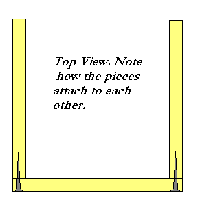
  1. Cradle and altitude trunnions
    1. The purpose of the cradle is to hold the tube steady but also allow for changing the altitude angle and changing the balance point when additional items are added to the telescope, and to allow the user to put the focuser at a convenient angle by rotating the tube.
    2. The cradle consists of four rectangular pieces of plywood that are glued and screwed to form a box that the tube fits in, and two altitude trunnions that each consist of a plywood disk and a ring cut from a PVC sewer pipe. The pipe fits onto the plywood disk and is held there by friction. See diagram below.                           make a dob pic 1
    3. Use 2-inch deck screws, and glue, to attach the 9+3/4” by 12” pieces of plywood to the 8+1/4” by 12” pieces of plywood. Three or four screws per edge should be enough. Use plenty of glue, and use a damp paper towel to wipe up the glue that oozes out. It is not necessary to counter-sink the screws. Make sure everything is lined up properly before inserting the first screw. If you want, you can nail in a couple of small nails (say, 2” long) to hold things in place before you put in any screws.
    4. Before attaching the plywood disks that hold the PVC plastic trunnions, it is advisable to draw the diagonals as shown. This will help you make sure that the disk is centered correctly.
    5. When the glue is somewhat dry, this all can be painted, inside and out.
    6. When the paint is dry, then you can attach the handle and fit the PVC trunnions onto the plywood disks. It is supposed to go on with difficulty, so that it won’t come off easily. It should not need to be nailed, glued, or screwed.
  2. Optical Tube
    1. The tube
      1. The tube itself is made of thick cardboard designed for casting cylindrical concrete columns. One brand name for these is Sonotube. When painted, it is strong, relatively rigid and light, and reasonably waterproof, and it’s quite inexpensive: $5 for a 4-foot length of tube. (Carbon fiber composite tubes, which are lighter, stronger, more rigid and much more waterproof, would cost nearly 100 times as much.) The purpose of the tube is to hold the optical components rigidly, in the proper alignment so that the user can look at things.
      2. A 1+1/2” diameter hole will need to be drilled near the front end of the tube for the focuser. Use an ordinary hole saw attached to an electric drill for this. If you are using a 3- or 4-vane spider, measure and drill the holes for this now.            make a dob pic 2
  • It is very important to paint the inside of the tube using flat black paint. I strongly recommend using latex paint so that any drips can be washed off with water, likewise the brush, and so that the fumes are not so bad. Two or more coats are desirable. However, the tube is quite long, and you don’t want to get paint all over your arm. How to reach the middle? One way is to tape your brush to the end of a dowel rod (or other scrap piece of wood) with duct tape, and use that to extend your reach. When you have finished painting the inside, leave the tube to dry in a horizontal position so that air can circulate; or else, if you want to let it dry in a vertical position, make sure that you put it on some little scrap pieces of wood so that air can circulate up and down the tube. Be sure to wash the brush as soon as you are finished painting. Use lots of water and even some hand soap and rinse it very thoroughly.
  1. The outside of the tube also needs to be painted. Any color will do – the wilder the better, in my opinion. See the previous remarks about latex paint. It is a good idea to let the tube dry in a vertical position, propped up on little scraps of wood. Be sure to paint the edges where holes have been cut and the ends of the tube; when the loose cardboard is impregnated with paint, it becomes much harder.
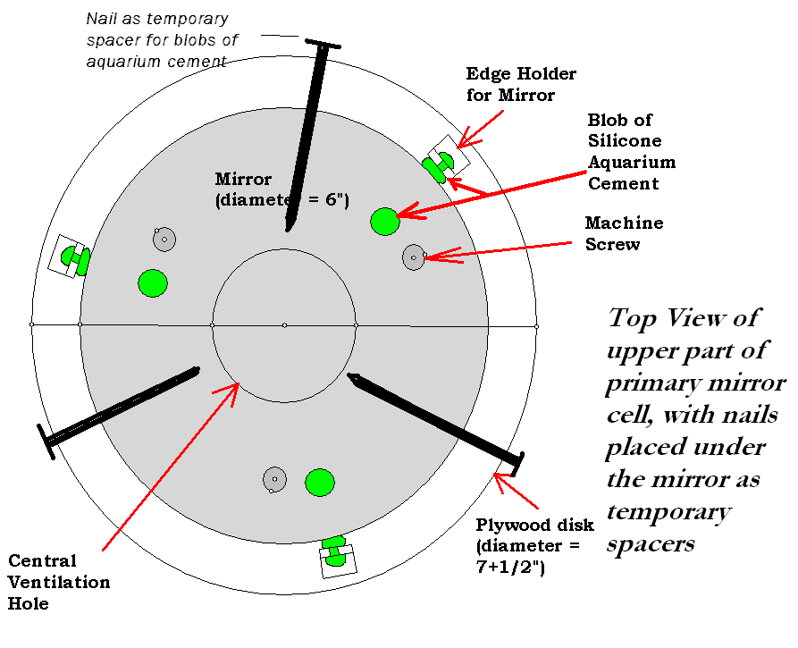
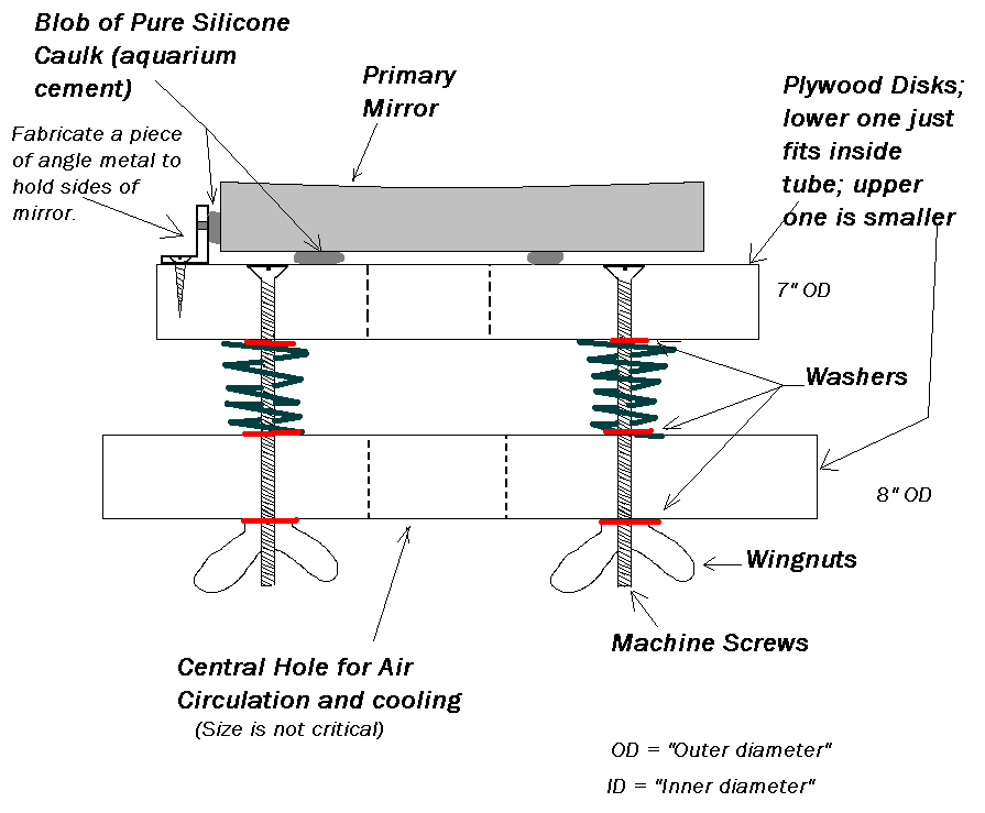
  1. Primary Mirror Holder
    1. The purpose of this item is to hold the mirror rigidly in the correct alignment, at the proper distance from the secondary mirror and the focuser, so that whoever is looking through the telescope can actually see correctly-focused and clear images of whatever it is they are trying to observe. It is not necessary to paint this part, but it won’t hurt, either. However, the parts where the silicone caulk will hold the mirror to the wood must NOT be painted, because the caulk does not stick well at all to painted surfaces.
    2. The mount consists of two plywood disks separated by springs and held together by machine screws, washers, and wingnuts. The upper plywood disk has an outer diameter about one-half inch less than the inner diameter of the tube; so that’s about 7+1/2”. The lower plywood disk has an outer diameter that is about the same as the inner diameter of the tube, so that’s just shy of 8”. Each disk should have a good-size hole drilled in the center for ventilation. The size of the hole is not critical – any size that you have a hole saw for will work fine.
  • The two disks also need to have 3 holes drilled in them at 120 degrees from each other so that the machine screws can go through. The hole in the upper disk should be countersunk so that the machine screw head will not protrude. The hole in the lower disk should be considerably larger than the screw itself, so that the entire assembly can be adjusted easily. Be sure to line the two disks up together before drilling the holes, and mark how they are supposed to go.
  1. A small piece of steel (or any other convenient metal) should be fabricated into an L shape, with a hole in both parts. The hole in the horizontal part will hold a single, small screw to attach the L to the upper plywood disk, and the hole in the vertical part will be used to squirt the silicone glue through, to hold the mirror in place.
  2. When the entire setup is assembled, except for the glueing of the mirror, then lay three ordinary nails underneath where the mirror will go, as temporary spacers. Squirt nice thick blobs of glue in the three locations previously chosen, then carefully place the mirror in the correct location. Then squirt three more globs of glue, one at each of the three L-shaped edge holders. Then put the entire assembly away somewhere level, safe, and dry, with ventilation and protection from dust, so that it will not be disturbed for a couple of days while the glue sets.
  3. See the diagrams for construction details, and below that for an example by a local ATMer, JCN.                                                                    make a dob pic 3Make a dob pic 4
  • The primary mirror cell is about the last thing to be placed in the telescope. It goes in AFTER the focuser and secondary are put in place, and after everything is assembled, painted, and dried. In my experience, it is not possible to calculate exactly where the mirror should go in the telescope; none of the formulas I’ve seen work exactly. The best one can do is to estimate it, but then the exact location will depend on your eyepieces, the height of your focuser, and your eyes. So, once the rest of the scope is together, you carefully slide the primary mirror cell – with its mirror in place – up into the tube to where you think it should go, and do a very rough alignment of the mirror by looking down the tube. Use shims to get it to stay in place temporarily, and try to focus on as distant an object as possible by daylight. To get it to come into focus will probably require pushing or pulling the entire cell forward or back. Then try the entire process at night, when you can see the moon or a very bright star such as Vega or Sirius. It will not focus the same way, I guarantee! When you have the mirror in such a location that stellar objects come into focus, THEN you can use deck or drywall screws to screw it permanently into place in the tube.

make a dob pic 5cell holder variant by JCN

  1. Focuser
    1. The purpose of the focuser is to hold an eyepiece at the very end of the voyage of all of those photons from outer space so that your eye can detect an image.
    2. Unless you are doing astrophotography, a simple rack-and-pinion focuser with a knob will do just fine. The standard size focuser and eyepiece for decent, smaller telescopes (under 12” diameter) is 1/25”. Plastic-and-metal ones work fine unless seriously abused. There are ones designed for refractors, and ones designed for reflectors. Get the latter type, unless you are building a refractor!
  • Use small nuts and bolts to attach them to the telescope tube.
  1. Unfortunately, some focusers will require a shim to be fabricated underneath so that there will not be a light gap between the focuser and the telescope tube. This all depends on the focuser and the tube you are getting.
  2. As mentioned earlier, you will need to cut a hole in your tube large enough to fit your focuser.
  1. End Ring
    1. The purpose of this is to strengthen the end of the telescope tube that points towards the sky.
    2. Use a decent-quality plywood and a router to cut a ring with a thickness of roughly an inch that will fit tightly onto the end of the tube. Our tubes are 8+1/4” OD, so that should be the ID of the ring. After routing it, sand it to remove burrs and splinters, fit it onto the tube, apply some glue and small nails, and let it dry.
  • Only make an upper end ring; not a bottom end ring, or else you won’t be able to view objects near the zenith.
  1. Mid Ring
    1. The purpose of this is to allow the telescope to stay in place at the chosen balance position, and to allow the user to rotate the tube and to adjust the balance if needed.
    2. The instructions for cutting this are very much like the end ring. The difference is that there should be a small amount of ‘play’ or room for the ring to move over the tube, so that with some force and perhaps a mallet it can be moved when desired. Thus its interior diameter should perhaps be 8+5/16” when cut. Paint will reduce that slightly.
  • The mid ring is NOT glued or nailed to the tube. It should be able to slide, with difficulty.


  1. Secondary Diagonal Mirror, holder, and spider
    1. The purpose of the secondary diagonal mirror is to re-direct the light from the object of interest out the side of the telescope, so that you can see the object without your head getting in the way.
    2. You can build this or make all of these parts. Unless you are very good with your hands and with making small metal parts, I suggest you buy them. The mirror itself is a true optical flat, and is easier to make on a machine than by hand.
  • Before putting this in place, it is necessary to find the exact center of the secondary mirror, and to measure the distance from this to the level of the screws that hold the spider in place against the wall of the tube. Measure and re-measure, then drill the appropriate holes, and fasten it all in place. (Remove the mirror itself while installing the spider vanes, so that dust and fingerprints don’t get on the surface of the mirror.)
  1. Finder Scope
    1. The purpose of the finder scope is to allow the user of the telescope to aim it at an object of interest. It gives the user a wider field of view than the telescope itself, which can have a field of view as small as hundredths of a degree.
    2. I strongly suggest a Telrad or other similar 1-power non-magnifying heads-up finder. These devices allow you to aim your telescope intuitively at familiar objects and then to star-hop to other objects. Then, as your budget permits, you can upgrade to other finders – and there is a wide variety to choose from!


  1. Rocker Box
    1. The purpose of the rocker box is to hold the telescope rigidly upright and to provide a place for the altitude trunnions to fit into, so that the telescope can be aimed up and down, and left and right, just like a cannon.
    2. The rocker box is made out of 4 pieces of ¾-inch plywood. It has a front, two sides, and a bottom, but no back and no top. The front is shorter than the sides, so that the telescope can be aimed at the horizon if desired. The pieces will be glued and screwed together. The two sides will have nearly semi-circular holes cut out of the tops to hold the trunnions bearings.
    3. Need to cut out the following:
  1. Bottom: one piece 11+1/4” by 10+1/2” plywood. A one-half inch diameter hole should be drilled at its exact center.
  2. Sides: Two pieces that are 11+1/4” by 33” plywood (can be a little longer if desired). Make it so that they are left-right symmetrical, so that the good side of the plywood will be facing out. Cut an arc at the top of each side to fit the trunnions.
  • Front: One piece 11+1/4” by 25” (this height can be changed, but should be about 8 inches less than the sides)
    1. Five or six deck screws, 2” long, on each vertical edge, should be enough. Be sure to use glue as well. The bottom edges could use about 3 screws per edge. Clamp the edges for about 30 minutes after glueing, and remove excess glue with a damp rag. Except for the underneath portion, this can be painted. After drying, this will be attached to the base plate.
    2. Two pieces of Teflon will make sliding contact with the PVC trunnions. They will be glued or nailed into place at the tops of the cut-out arcs at the tops of the side pieces.

make a dob pic 6

make a dob pic 7

  1. Base Plate, or Azimuth Disk
    1. The purpose of the base plate is to allow the rocker box to swivel left and right, so that the user can aim the telescope at anything he or she wants to look at, in any part of the sky.
    2. This base plate is the invention of John Dobson, a master scrounger, all-round eccentric amateur astronomer, and former monk who lives in California. It consists of a downward-facing surface of Formica, Wilsonart, or some similar type of counter-top laminate, resting on three Teflon pads attached to an upward-facing surface. Unlike telescopes made from metal parts, this mounting rotates very smoothly and does not have any backlash at all. That is, if you move the telescope to a given position and let it go, it will stay where you leave it.
    3. To cut out:
  1. two 15-inch diameter circular disks from the same ¾” plywood. The precise size is not critical. Using the jig that we have in our shop, you need to drill a ½-inch hole at the exact center of the disks first, and then cut them out, only cutting through half of the plywood at a time, flipping them over for the second cut.
  2. One piece of countertop laminate – any type will do – a square 16” by 16” is fine.
    1. Choose which will be the upper disk, and which part of that disk will be facing up. Use paintbrush to coat the other side of the wooden disk with a smooth layer of latex-based contact cement. Also paint the back side of the countertop laminate. Let the two surfaces dry until no longer gooey to the touch. Then place the laminate on top of the wood and press hard all over (there are special rollers for this, or you can use heavy glass bottles or heavy metal cylinders) so that they make good contact.
    2. Use a trimming router to trim off the excess laminate.
    3. Then use relatively short screws to attach the top disk to the bottom of the rocker box. Make sure the hole in the bottom of the rocker box lines up with the hole in the center of the top disk. Feel free to finish drilling the center hole through the laminate.
    4. The bottom disk will receive three pieces of Teflon pad around the edges at 120-degree intervals.
  1. Legs
    1. The purpose of the legs is to give the entire telescope a bit more stability and to raise the base of the telescope up off the ground by a few inches.
    2. I suggest using a 2×3 or 2×4 and cutting three pieces about 9 to 10 inches long, then cutting them into an L-shape or a shape a bit like a hockey stick, as shown here:    make a dob pic 8
    3. File or sand the legs so that folks won’t get splinters. Make sure there is clearance for the central pivot bolt, the aluminum plate, the nuts, and the lockwasher. Position the 3 legs 120 degrees apart, then screw and glue them into place. Some of the screws will need to be rather long.
    4. Attach the Teflon pads right over the legs themselves, as close to the edge of the disks.
  1. Now paint everything and let it all dry.
  2. Align your optics.
  3. Then go observe!

(<== Link back to the beginning of this series of articles)

Build Your Telescope Tube and Mount

16 Tuesday Dec 2014

Posted by gfbrandenburg in History, Telescope Making

≈ Leave a comment

Tags

alt-az, company 7, equatorial, hands-on-optics, plywood, teflon

7. Build the scope

A. There are many, many books and articles and websites devoted to the many, many ways of building your telescope tube and mount. We have quite a few of these books in our library, and you should definitely study them! In addition, public star parties put on by NOVAC, NCA and other local clubs often have home-made telescopes on the field, and you can ask the makers of those scopes how they did it. Fortunately for us, John Dobson came up with an excellent way of making inexpensive, easy-to-build and easy-to-use telescopes of the Newtonian model, even if he was a nut-case. Willmann-Bell publishes quite a few such books.

B. I strongly recommend an alt-az telescope mount for visual use, rather than an equatorial mount on a pier made of plumbing parts, as people used to make in the 1940s through the 1990s. (As noted earlier, if you want to do astrophotography, you will need a much more complicated and much more expensive mount that tracks the stars precisely. Building such a mount yourself is exceedingly difficult and requires precision machining and electronics!) Most important: plan to make a telescope that is easy to use and not too complicated to build! Using slight modifications of existing plans is much easier than trying something completely novel in design. If you strive for originality, you can be sure that you will need to modify and re-build parts of your invention, perhaps several times, because of problems that you didn’t consider or notice originally. (Think about what a nightmare it would be to drive a Model-T Ford automobile, the first real mass-production car, with all of its nutty and dangerous defects, compared to the comfortable and safe and reliable car that people drive today!)

C. I have a set of plans for a simple 6” Dob on this very blog. (Click for link)

D. At the CCCC, we also have a fairly decent set of hand and power tools for working with wood and metal, so you can make the rest of the telescope here if you like. Be careful, and follow safety directions!

E. We even have a wonderful assortment of ‘oops’ paints from hardware and paint stores, if you don’t mind the ghastly colors.

F. You will need at least half of a sheet of 4’ by 8’ plywood for the scope. The plywood can be any type you like, but don’t get a sheet that is warped or wet or too thin. Nice plywood like Appleply or Baltic Birch can be expensive, but it is strong and looks quite beautiful when varnished. Three-quarter inch thickness is standard, but it’s generally sold as a weird number like 23/32”.

G. You will also need the following commercially available items, some of which we usually have on hand, marked by “UOH”.

  1. Diagonal secondary flat elliptical mirror (we have a few)
  2. Secondary mirror holder
  3. Spider
  4. Focuser
  5. Eyepieces
  6. Finder scope(s) (I recommend a 1-power finder like a Telrad or a Red Dot finder, as well as another finder scope that magnifies about 5 to 10 times)
  7. Possibly a Barlow
  8. A few pieces of Teflon UOH
  9. A few square feet of Formica or the equivalent UOH
  10. Miscellaneous screws, nuts, bolts, screws, glue UOH
  11. Guidance UOH
  12. Paint UOH
  13. Random wood scraps, including a short 2-by-4 UOH
  14. For the mirror holder, you need: Three compression springs; 3 flat-headed machine screws; 9 washers; 3 wingnuts; and a small fresh tube of pure-silicone caulk or aquarium cement

H. We are very fortunate to have a local specialty store that sells telescopes and accessories to the public, called Company 7 . It’s located near Laurel, MD and has an amazing display of rare telescopes. Please shop there! (In other words, don’t talk their ears off getting their advice, and then order an item online because it’s a few dollars cheaper!)

(Link forward to the next section ==>)

(<==Link back to the previous section)

Aluminization

16 Tuesday Dec 2014

Posted by gfbrandenburg in Telescope Making

≈ Leave a comment

Tags

Aluminization

6. Aluminization

A. Once the mirror is done, you need to put a reflective coating on it. We have a device that does that: a military- and university-surplus vacuum chamber and aluminizer that we have been keeping alive for about 30 years or so, shown below. Briefly, this is what we do: essential atm steps aluminizer

B. We clean the mirror very, very thoroughly.

C. We put it into the vacuum bell jar in a special jig that holds it at the top, facing downwards;

D. Pump out almost all of the air with a mechanical pump. This gets the pressure from 760 mm of mercury (normal pressure, 760 Torr) down to about 0.1 mm of mercury (0.1 Torr).

E. While pumping, we zap the mirror surface with a high-voltage A/C plasma which further cleans and prepares the glass to accept the aluminum coating. This looks like the Aurora Borealis.

F. We then turn on the diffusion pump, which works by somehow capturing individual molecule of air in a condensing mist of expensive silicone oil that was boiled at very low pressure. It sounds like magic, but it works to get the pressure down from 0.1 mm of mercury all the way to 0.00008 mm of mercury, which is what we need for the last step.

G. Then we slowly heat up a special tungsten filament coil that has a slug of pure aluminum wire inside the coil. The coil melts the aluminum, which coats the tungsten coil and then boils off into the vacuum, in all directions. A small part of that aluminum vapor hits the mirror, and sticks to it in a very thin layer.

H. We then close down the diffusion pump, close and open various valves, and wait for the air inside the chamber to equalize with the air outside, so we can open up the chamber and remove your mirror.

I. You should be very gentle with the coating, especially at first. Resist the urge to wipe it clean if dust gets on it. It will be about 85-90% reflective, and will stay that way for years. If there were any nearly-invisible scratches left on your mirror after polishing and figuring, they will be highlighted by the shiny aluminum layer. They won’t have any optical effect, but they will make you feel bad. Keep the mirror protected from fingers, sneezes, dandruff, snot, and dust. Don’t let anything touch the surface, even soft cloths!

(Link forward to next section ==>)

(<== Link back to the previous section)

Figuring (parabolizing) Your Mirror

16 Tuesday Dec 2014

Posted by gfbrandenburg in History, Telescope Making

≈ Leave a comment

Tags

couder, foucault, parabolization, testing

5. Figuring and Testing

 A. Polishing pads do a great job of polishing out the pits, but they tend to leave a rough surface that is not a true paraboloid or even a section of a sphere, unless you are very, very lucky. Most folks will switch to a pitch lap for the figuring process, which involves removing sub-microscopic amounts of glass from various zones on your mirror, in order first to make it into a section of a sphere, and then into the bottom of a paraboloid – the only geometric figure that will reflect all of the rays that come from distant stars onto a single focal point. Many treatises have been written about figuring, and I’m not going to add to that list. “Understanding Foucault” by David Harbour gives an excellent explanation of the figuring process, as does Mel Bartels here. However, here are some of the basics:

B. You will need a pitch lap, made either of Gugolz or Acculap or Tempered Burgundy pitch. The first two are synthetic products whose composition is probably secret; the third one is made from the sap of coniferous trees. I’m not going to describe the process of making a pitch lap here, but I combine some of the methods of Carl Zambuto and John Dobson when I make a new one; you can watch it as we do it for you. It’s much less work if you can use a pitch lap that was made by or for someone else who has finished their own project. Sometimes a previously-used pitch lap will have sat around too long and might need to be scraped off and remelted. We generally use roughly square facets, which allow the pitch to flow better and conform itself to your mirror. Without the facets, any high points on the lap have a hard time being lowered. We also tend to use netting or a single-edge razor blade to make minifacets, which further help the lap to conform to the mirror.

C. Pitch is weird stuff. When it’s warm, it flows and it’s very sticky. When it’s cold, it is fairly hard, and you can shatter it with a hammer. If you leave a pencil or a coin on a pitch lap overnight, the next day you can see all of the details of the pencil or coin reproduced perfectly in the pitch. We want the lap to conform itself to your mirror. Then we use the pitch lap to remove all of the irregularities that were left by the polishing pads. So, we warm up the pitch lap to soften it a bit (using a heat lamp or hot water), spread Cerox or rouge onto your mirror, and then press the two together briefly but firmly. We often use some netting to create micro-facets, which help the pitch conform to your mirror even more.

D. The figuring stage can severely try your patience, especially if the tests show a surface that looks weird. But relax! If you persevere and don’t drop the mirror on the ground, success is guaranteed, since it’s just a matter of removing the correct millionth of an inch or two (much less than a micrometer) of glass from the correct zonal ring to achieve near-perfection. One needs to make sure that the lap actually conforms to the mirror; bad contact between the two can cause trouble, and so can a pitch lap that is too hard, too soft, or too thin. All of those are fairly easily fixed, with remarkable results. And we are here to help.

E. One major problem that can affect mirrors is a Turned-Down Edge (TDE). Opinions vary on what causes this dreaded condition, but the evidence suggests to me that TDE appears when the lap is exactly the same size, or slightly smaller, than the mirror itself. To avoid a TDE, do not chip off the parts of the pitch lap that ‘mushroom’ out past the edge. Let them stay there.

F. You will be instructed in a specific set of strokes which will first make your mirror into a sphere. Then, you will be instructed in a different set of strokes that will make your mirror into a good approximation of a perfect paraboloid. Texereau, LeCleire, and many other books describe those strokes. So did Leon Foucault in his 1859 article, which you can find on this blog/website. In our workshop, we will test your mirror frequently with a combination of tests, many of them invented by Foucault but later modified.

G. A very fast qualitative test is the Ronchi test, which you can look up. It gives you almost instant feedback on the presence or absence of bad features like turned-down edge (TDE), zonal defects (high or low rings), astigmatism (lack of symmetry), roughness, and so on. It will tell you whether your mirror is a sphere or not – if the Ronchi lines are perfectly straight, then you have a sphere. If they are not straight, then the test can tell us if your mirror is on the way towards being an ellipsoid with the long axis perpendicular to the mirror (or parallel to it), or a hyperboloid, or your goal, a paraboloid. There are several computer programs that provide simulations of what a perfect mirror should look like under the Ronchi test, but I’ve found you can’t always trust those simulations. RonWin is one such program, and Mel Bartels has another on one of his web pages.

H. A more time-consuming test that I find is necessary is the Foucault test as modified by Andre Couder, also known as the numerical knife-edge test with zones. If the Ronchigram looks good, and the numbers in the knife-edge zonal test are also within acceptable limits, then the mirror is done. A slight modification of this test is known as the Wire Test, which works well on fast mirrors. David Harbour’s article does an excellent job of explaining this test. One can use a pinstick method for marking the zones, or one could write directly on the mirror with a Sharpie, but we use a version that uses cardboard masks with holes cut out at carefully-measured zones.

I. We have tried a number of other tests, such as the double-pass autocollimation test, the Mobsby Null test, and the Bath Interferometer test, and have had difficulties getting good results with them. Therefore, we are continuing to use the Ronchi and Knife-Edge Zonal tests.

J. However, the best test of any mirror is the Star Test, which is the subject of an entire book by Richard Suiter. Some do this in the daylight, using sunlight reflected from very distant insulators on electrical poles. Most do it at night, but it requires steady air (‘good seeing’) and a clear sky as well. The Star Test is much easier to perform if the mirror is already aluminized and in a working telescope, which brings us to….

(Link forward to next section==>)

(<==Link back to previous section)

Polishing Your Mirror

15 Monday Dec 2014

Posted by gfbrandenburg in Telescope Making

≈ Leave a comment

Tags

barnesite, cerium oxide, Hastillite, pitch, Polishing, polishing pads, rouge

4. Polishing

 A. By the time you are at 9 to 3 microns, you will notice that your mirror is translucent but not transparent. If you wet your mirror, then you can read text through it, but the surface is still not as smooth as, uh, glass. In order to get your mirror optically smooth, you will need to change from fine grinding to polishing with a soft lap which holds the abrasive in place, instead of allowing the abrasive to roll between the two pieces of glass. Leon Foucault describes using paper laps for this purpose; others have used honeycomb foundation, shower curtains, and even road or roofing tar. There are numerous types of optical pitch made by various companies out of of tree sap, petroleum, or some secret proprietary ingredients.

 B. An innovation developed at the Delmarva ATM group is to save time by using ophthalmological polishing pads (links here, or here, or here) for the initial polishing. It cuts the number of hours of polishing roughly in half, which is great, because polishing with a conventional pitch lap can take about one hour per linear inch of diameter, or more. (So, roughly six hours for a six-inch mirror.) The amount of time required to fully polish a mirror is greatly dependent on the amount of force applied by you, the mirror-maker.

C. To use the polishing pads, you clean the tool very thoroughly with isopropyl alcohol or denatured ethanol or acetone to remove all traces of fingerprint oil. Wash your hands thoroughly. Consider using latex gloves and tweezers. Get scissors and a clean, sharp single-edge razor blade. Carefully peel a pad from its roll, trying to touch as little of the adhesive side as possible. Press it down onto your tool slightly off-center. Then continue applying pads with one big caveat: NO PADS MAY OVERLAP OR TOUCH. It is OK to trim the pads before applying them, or afterwards, and it’s OK to be artistic about it. Do NOT strive for symmetry here – it will cause problems with your mirror, believe it or not. Don’t make pieces that are very small; the size of your smallest fingernail is about the smallest piece you would want. Once they are all in place, use a clean artist’s J-roller to press them all down, firmly.

D. You will now need a polishing stand with cleats to hold the mirror in place, because you are going to be pushing quite hard on your mirror or lap. Without the cleats, your project will end up on the floor, broken. In the DC ATM class, we use lazy-Susan turntables that rotate around a fixed pivot point to make it easier for you to rotate mirror and the lap in a regular manner. You should also cut some shelf-liner material to fit underneath your mirror and tool, to prevent irregularities in the wood substrate from deforming your mirror.

E. You will use a slurry of Cerium Oxide (formula CeO2 also known as cerox)* mixed in distilled or purified water. Don’t use tap water because it might contain particles that come from the pipes and thus might scratch your mirror. It is totally non-toxic. Mix it up fairly thick, something like heavy cream. Do not apply very much liquid to the pads; if you do, the petals of your polishing pads will come off of the glass. Do polish hard, and polish long. Rotate everything as usual, and alternate tool on top with mirror on top. Do NOT let the cerox or even individual droplets of water air-dry on your mirror: they will etch the surface somewhat, and then you will have to polish some more!

F. When are you done? Simple: you are done when it’s fully polished out. How can you tell if you are polished out? Here are two simple tests:

G. Use the highest magnification and best illumination you can on your microscope, and carefully inspect the mirror surface for any remaining pits or scratches. If you see anything at all, it’s not done. (If you see something that looks like a white caterpillar, relax: it’s probably a bit of lint from a paper towel! Wipe it off and look again!)

H. The laser test uses a red or green laser shining into and onto the surface of the mirror from about a 45-degree angle. Ideally, the light should pass through the surface leaving behind almost no trace of its passage. If you see a bright spot where the laser hits the surface of the mirror, then you need to keep polishing. Or else the mirror is dirty.

* Note: there are several other commonly-used polishing compounds, such as zirconium oxide, red rouge, black rouge, and even Barnesite. Compounds that are labeled ‘cerium oxide’ often have a fairly substantial proportion of other ‘rare earth’ oxides in, since they are so difficult to separate chemically and probably act in the same way. Thus one cerium oxide preparation might look white as talcum powder, while others will appear pink or brown. Red rouge gives a very fine polish, but it’s slow-acting and extremely messy, staining your hands and clothes — the latter, often permanently. Black rouge is even finer and messier. Zirconium oxide acts faster than red rouge but slower than cerium oxide. I haven’t used Barnesite much, but it’s hard to get, messy, and almost as slow as red rouge. Professionals working on the finest telescopes in the world have abandoned red rouge because of its mess. These professionals can also afford extremely fine proprietary mostly-CeO2 slurries that cost a LOT, such as Hastillite. We can’t afford that. So we tend to use cerium oxide at first and switch to rouge when doing the final figuring.

(Link forward to next section ==>)

(<== Link back to previous section)

Fine and Intermediate Grinding of Your Mirror

15 Monday Dec 2014

Posted by gfbrandenburg in Telescope Making

≈ Leave a comment

Tags

Grinding, Grit, Mirror

3. Grinding (intermediate and fine): Once you have reached your goal for the sagitta, and inspected it, then it’s time to move on to the next smaller grit size and to a more conventional grinding technique. First of all, throw away all of the used newspaper, rinse out the water bucket, wipe off and put away the grit container, and clean off the workbench. Wash or rinse your hands, and make sure that your clothing does not contain the previous grit size. Then get new clean newsprint, clean water, and the next smaller grit size. Again, dampen the newsprint to keep the mirror and tool from sliding around.

 A. You will NOT be using the circular stroke once you are past the hogging-out stage. You will instead be doing a center-over-center stroke, where the mirror or tool that is on top is pushed back and forth in a straight line away and towards your body, such that the top piece of glass will project forwards, and then backwards, by about 1/6 of the diameter of your mirror. You will do this for maybe 8 to 10 times, then rotate both to avoid astigmatism. With 6”, 8”, and 10” mirrors, a decent rule of thumb is to budget an hour of grinding per grit size, or more. Otherwise, the grinding sequence is the same, including the regular rotation process.

 B. Here is one possible sequence of grits for an 8” or 10” mirror, but there are other possibilities. We have lots of different sizes of grits, made by various manufacturers over the past 50 years, and so we use a lot of steps. Other people don’t have as many sizes, and they will use fewer steps, but take longer at each grit size. The 60-400 grit sizes are generally made of silicon carbide (trade name Carborundum, formula SiC, which is also made into jewelry under the chemical name Moissanite or names like “Diamond Aura). Past that, most grits are aluminum oxide. Notice the different methods of measuring the grit – up through 400 grit, the number theoretically means the number of grains that it would take to make one linear inch. The micron sizes are in millionths of a meter, or thousandths of a millimeter. I have collected a number of tables that supposedly show how these sizes are related. Unfortunately, the tables do not agree with each other. We generally prepare slurries with the micron-measured grits; this means that you need to shake up the slurry before applying it to the work, but it also means you have fewer chances to contaminate your work.

 60 grit  (hogging out)

80 grit

120 grit

220 grit

320 grit

400 grit

30 micron

25 micron

17 micron

9 micron

5 micron

3 micron

 C. When you get into the micron sizes, you need to be on guard against the mirror sticking to the tool. If you feel them beginning to ‘catch’ and stick, then immediately separate them and add more slurry. If they do stick together, it’s merely a pain in the tush, not a disaster – we just use bar clamps and pieces of wood to carefully press the tool and mirror past the other. If this happens at home and you don’t have a long bar clamp, you can instead put them both into a clean bucket of warm water with a drop or two of detergent and wait for a while, then push; alternate with a bucket of cool water with some detergent and wait for a while, then push; repeat as necessary until they come apart. Don’t use boiling or near-freezing water because the thermal shock could possibly crack either the tool or the mirror.

 D. Be careful about contamination. It will only take a single grain of 120 grit to make a nasty bunch of scratches in a mirror that you are fine-grinding at 5 microns! Be paranoid! Dust particles can linger anywhere! Wash your hands frequently, don’t re-use paper towels that have dropped on the floor, clean off your work surface after you are done, and use plenty of clean newsprint to cover the workbenches. (However, a few scratches will NOT measurably damage the optical qualities of your telescope. It’s much more important that the overall figure be good.) Also watch out for grit or sawdust or metal chips sticking to your clothes and hair. To help prevent contamination, we have installed a large screened tent canopy. Only work under there for polishing and figuring.

 E. When to move to the next grit? Use your naked eye, and/or an inexpensive illuminated microscope to check for uniformity of wear all over the mirror before proceeding to the next step. With some of those microscopes is possible to use a cell phone to take photos of the texture of the glass. Make sure the texture is the same near the edge of your mirror as it is in the center. If it’s not, keep grinding for a while.

 F. You won’t be able to change the focal length very much once you are past 120 grit, so use your spherometer and a combination of work with tool on top (TOT) and mirror on top (MOT) to get the focal length where you want it to be before you move onto 220 grit. Remember: MOT will make the sagitta deeper, which means a shorter focal length, and TOT does the exact opposite.

(Link forward to the next section ==>)

(<== Link to go back to the previous section)


Rough Grinding of a Telescope Mirror

15 Monday Dec 2014

Posted by gfbrandenburg in History, Telescope Making

≈ Leave a comment

Tags

Hogging, Rough Grinding

(Part two of my description of the essential steps in making a telescope)

essential atm steps calculate sagitta

2. Hogging Out means making your mirror blank have roughly the proper concave shape for the focal length or f-ratio that you want. There are many articles and web pages on this, which you really should look at!

 A. The math is important: you want your mirror to be a parabola, and the equation for the depth (or sagitta) that you must grind into the glass isn’t too difficult. First of all, “f-ratio” means the ratio between the focal length and the diameter of the primary mirror. So if you plan on making an 8” diameter mirror with a 40-inch focal length, 40” divided by 8” gives you an f-ratio of 5. With no units. If you wanted a 10” diameter mirror with the exact same focal length, we would call that f/4. For the sagitta (depth of curve) required, it’s easiest to use the formula for a parabola facing upwards with its vertex at the origin, namely,  . and you will need to do a little math[1]. Here’s a diagram that I hope will help:  It is supposed to show a mirror (blue) with an insanely short focal length of 7.03 inches and a diameter of 10 inches. The sagitta is the depth at the center of the curve, or length CB, which will be the same as DE and GF. Using the formula   , and plugging in 5 for x and 7.03 for F, we get that y (the sagitta) would be about 0.889 inches, a bit more than 7/8” of an inch of glass to remove. And that’s what we see in the diagram, too, if you look carefully. For a more realistic example, let’s suppose we wanted to make a ten-inch mirror with a focal length of 60 inches (which means that the scope would be about 5 feet long, or roughly 1.5 meters). In that case, we would get a sagitta of about 0.104”, a bit more than a tenth of an inch. You will need some way of measuring the sagitta. We use some spherometers that we fabricated from bits of metal and various dial indicators. Some people use a collection of automobile mechanic’s feeler gauges and a straightedge that goes across the entire diameter. Note that a spherometer will typically NOT measure the entire diameter of your mirror, so you need to account for that smaller diameter. You should calculate and record what your numerical goal is for your chosen method of measurement. However: one nice thing about Newtonian reflectors is that the exact focal length isn’t very important – unlike the other telescope designs, where any deviation from the designed model will cause the project to fail catastrophically. A 6” f/8 scope will work just as well as a 6” f/8.15 scope or a 6” f/7.7 scope; the only difference will be that the first scope tube will be about 48 inches long, the second one closer to 49 inches and the last one closer to 46 inches long.

 B, To grind the mirror, we use relatively coarse grit (silicon carbide, which is not toxic at all) mixed with ordinary tap water. The water acts as a lubricant and also to keep down the glass dust – silica dust causes very serious lung problems if it’s dry. So we keep it wet. We begin with either 50, 60, or 80 grit, depending on the size of the mirror. We put the tool (another cylindrical piece of glass or ceramic, or else something we cast from dental plaster and hard ceramic tiles) on many thicknesses of clean newspaper, on top of the workbench. We dampen the newspaper so they won’t slide around. We sprinkle some water onto the tool, and spread it around with a finger. Then we sprinkle some grit onto the water and tool as if we were liberally salting a dish we were cooking or eating. Then using both hands, we carefully place the mirror face down on top of the tool. We use both hands to make the mirror travel in a circular path in either direction for about 6 turns, grinding the center of the mirror mostly against the edge of the tool. (This needs to be demonstrated!) Wide strokes are good, but the center of the mirror must not get too close to the edge of the tool. At first this motion will be very, very noisy, which is fine. However, after perhaps 20-30 seconds, the noise will decrease. This means that the largest grains of grit have quickly been shattered, and they have also created gouges and fractures in the glass. After a minute or so, you need to separate the mirror and the tool and add some more grit and water, and continue the hogging out. After about 30-40 minutes, it is a good idea to rinse off the mirror, dry it thoroughly, and measure the sagitta with a spherometer to see how much progress you have made. It is a good idea to have a plastic bucket available that you can fill with water and use to rinse off the mirror and tool. The ground-up glass and grit will make a muddy slurry, which will eventually slow down the grinding process.                         essential atm steps grinding

 C. Try not to wrap your hands around the edge of the mirror towards the edge, if at all possible. This will heat up the edge of the mirror, making it expand, which can cause bad, unexpected results.

 D. Systematic rotation is super, super important: develop a method of methodically rotating the mirror and the tool with respect to each other, to the table, and to your body, so that you do not develop astigmatism! There are many ways of doing this. If we had barrels, you would be walking around the barrel. We don’t. We have large, heavy work-benches instead. I like to rotate them both in the same direction, like the hands of a clock, with the top piece of glass going a little faster than the bottom one. Do it systematically, NOT randomly. One way: do about 8 circular strokes. Then center the mirror on the tool. Turn the lower piece of glass to the left by about 15 degrees (1 hour on a normal clock face); then turn the upper piece of glass about 10 more degrees. Then grind away for 8 more circular strokes. Then turn the lower piece of glass to the left by about 15 degrees, and the upper piece by about 10 more degrees. And repeat, again and again. If you have a barrel to walk around, you would do this differently.

 E. It is possible to overshoot your goal when you are doing this initial hogging step. In fact, I recommend overshooting it by perhaps 5 thousandths of an inch, since the hogging stroke does not create a strictly spherical shape. But it does remove a lot of glass very quickly. If you end up much deeper than you intended, then put the mirror on the bottom and the tool on top and continue. Alternating tool on top and mirror on top will allow you to reach you goal as closely as you desire.

 F. Beveling the edge: if you have a sharp edge on your mirror or tool, then you will produce little shards of glass, much like making flint arrowheads. These shards will cut your fingers, and they will also scratch your mirror. Therefore, it is necessary to make sure that the edges of your mirror and your tool (front and back) are beveled or chamfered. There are many ways of doing this. You can use sharpening stones or wet-dry sandpaper, or you can put some water and grit into the wok that one of us banged into a smooth curved shape at his blacksmith shop. However you do it, it doesn’t take too long, and it will prevent lots of problems. You may have to renew the bevel after a while. Keep it around 1/8” (a few millimeters).

[1] If you are interested, I could show you how to derive this formula simply by using the Pythagorean Theorem.

(Link forward to the next section ==>)

(<== Link back to the previous section.)

Major Steps in Making A Telescope – According to Me

15 Monday Dec 2014

Posted by gfbrandenburg in Telescope Making

≈ Leave a comment

Tags

Planning, Telescope

ESSENTIAL STEPS FOR MAKING YOUR OWN TELESCOPE

By Guy Brandenburg

[Guy is the main telescope-making instructor at the amateur telescope-making (ATM) workshop sponsored by the National Capital Astronomers and currently housed at the Chevy Chase Community Center in Northwest Washington, DC. This guide is based on what he has gleaned by reading a variety of books on telescope making, as well as instruction by Jerry Schnall (his predecessor in this workshop), watching demonstrations at Stellafane, his own participation in two Delmarva Mirror-Making Marathons, visits from other ATMers to our workshop (including John Dobson), a tour of a commercial optical factory near Bel-Air, MD, and a visit to the Chabot telescope-making workshop in Oakland, CA. He has tried to steal good ideas from all of them and not to insert too many bad ideas of his own.]

  1. Plan your project by looking at various home-made and commercial telescopes, either in person or in books or magazines or on-line. Star parties put on by local clubs often will have some home-made telescopes on the field, and their owners/makers will be delighted to tell you what worked well and what they would wish to modify one day. Decide what size and focal length you can afford to make and can actually manage to carry around in your car or your hands, or install somewhere permanently. A Newtonian reflector is by far the easiest type of telescope design to make yourself. If you keep at it and don’t drop the mirror on a hard floor, you are pretty much guaranteed success and a well-performing telescope. All of the other designs (refractors, cassegrains, catadioptrics, etc.) are much, much harder to make and can fail for reasons that are very hard to figure out. Larger-diameter scopes are more expensive, heavier, and take more time to make, but you can see more detail and dimmer objects, too.
    1. Costs: If you are thrifty and crafty, you can definitely make a telescope of a given size for less money than one you purchase, but if you insist on the finest and most expensive components (exotic wood, for example), you can end up spending much more. Fifty years ago, the only way that the average person could afford to own a telescope was if they made it themselves; commercial 6-inch scopes sold in the 1950s for prices that are equivalent to about $2,000 in today’s money. Today, a six-inch commercial telescope and mount costs much less than that, and the prices of Pyrex-equivalent mirror blanks have recently tripled. A recent study in Sky & Telescope found that the biggest potential savings are for large telescopes, but a lot depends on one’s ability to scrounge and find inexpensive, but good-quality, components.

 B. Time: It’s not possible to say exactly how long any project will take. However, I always find that everything that I make, takes longer than I originally estimate, which is known as Hofstadter’s Law. When I made my first telescope, a 6” f/8, I kept notes on how much time I spent on grinding, polishing and figuring, and later added that all up: 30 hours. My second telescope, an 8” f/6, took me 40 hours. But keep in mind, those totals only count the time I spent actually pushing glass, not the time planning things, thinking about things, discussing the project, taking Ronchi and Foucault measurements, setting up the work, and cleaning up after a grit. They also did not include any of the time I spent on making the tubes and mounts or aluminizing the mirrors or learning how to use the telescopes in the first place. Obviously, you might take less time than me, or longer.

C. Longer focal length for a given diameter means sharper images of stars and planets, and usually an easier job of grinding and figuring, and they work well with less-expensive eyepieces, and the scope will work even if not perfectly collimated (aligned internally), and you won’t have problems with coma. However, it also means dimmer images with narrower fields of view, and objects will remain visible for shorter lengths of time, requiring constant adjustment; also the scope will be longer, heavier, and harder to maneuver. A focal ratio of 6 is considered by many ATMers to be an intermediate one.

 D. A shorter focal length for a given diameter means brighter images, a wider field of view, and a shorter, lighter telescope that is easy to carry around. However, the figuring process will be more difficult, collimation will be more critical, and coma will be a problem at the edges of your field of view. You may need to use additional tests to verify that your mirror is in fact well-figured.

 E. The difficulty, cost, weight, and amount of time needed to make a scope is roughly proportional to the cube of the diameter, which means that a scope with a 12-inch diameter mirror will be about 8 times harder, heavier, and more expensive than a 6 inch diameter telescope. On the other hand, its light-gathering power is proportional to the square of the diameter, so the 12-inch mirror will gather four times the amount of light than a 6-inch mirror, which in practice means that you will see stars and other objects a magnitude or two fainter with the larger scopes.

 F. As you can see, in astronomy, there are trade-offs. There is no car, no boat, no garment, no athlete, and no telescope that is BEST for ALL purposes. For example, a scope that is really good at providing a wide-field image of the Pleiades won’t do well at imaging the bands and festoons on Jupiter. Just setting up a huge scope 20” or more in diameter is a major undertaking and probably requires a step-ladder, whereas a 6” Dob can be set up and ready to go in about a minute by a sixth-grader. A large Dob is going to do its best work at a dark-sky location like the Rockies or parts of West Virginia. A computerized go-to scope, which you are probably not going to be able to build yourself unless you have some amazing skills in machining, computer programming, and electrical engineering, can work anywhere. Your goal should be to build a telescope that will be used!

 G. Rather important: a home-made Dobsonian-mounted Newtonian reflector is not really suitable for astrophotography. For that, you will need a very expensive equatorial mount as well as a digital camera of some sort (DSLR or CCD or dedicated web-cam) and, usually, a computer and a power supply. A “Dob” is GREAT for optical viewing with your eyes, and you don’t have to spend the entire night doing polar alignment, taking flats and darks and multiple guided exposures of the same object for hours on end with an expensive DSLR or CCD camera or dedicated web-cam; nor do you have to spend hours and hours learning how to digitally process all those digital images. Instead, you LOOK with your eyes, and you can look at dozens of different objects in a night, without fussing with electronic gadgets…

 H. You will need to decide on the materials for your mirror: plate glass (relatively cheap but usually no more than ¾” thick), Pyrex or its generic equivalents, or a relatively exotic material such as ‘fused silica’ (i.e. quartz) or a really exotic material like Zerodur, Cer-Vit, or BVC. For several decades, ATMers used full-thickness Pyrex mirror blanks produced in massive amounts by Corning Glass. They were relatively inexpensive, durable, and had low thermal coefficients of expansion. Unfortunately, Corning has stopped making Pyrex, and the generic replacements known as Borofloat and other trade names are now made overseas in considerably smaller batches, so the price for a full-thickness borosilicate crown glass equivalent to Pyrex has tripled or quadrupled. It turns out that modern float glass (also called plate glass) works quite well for making telescopes, unlike the wavy window-pane glass of 80 years ago. The term “float” means that the glass is made in a continuous process and is annealed and manufactured to be extremely flat and homogeneous by, yes, floating it on a bed of pure molten tin. You do have to be more careful about preventing astigmatism, and must cool the glass down to ambient room temperature in a bath of cool water whose temperature you have measured, but many excellent mirrors have been made using ¾”-thick plate glass cut into disks by the water-jet method at a local glass fabricator.

 I. Instead of making your own mirror, you could buy a used or new one that someone else made. There are generally several used primary mirrors for sale at any given time, of various sizes and prices, at websites like eBay, Cloudy Nights Classified,  or Astromart. Astromart has the widest selection, but you have to pay a fee (about $10-$20 per year) to post or respond to ads. Cloudy Nights has a lot of forums where people express their opinions on subjects astronomical, and many of them are probably correct. (Definitely worth reading in any case!) Some of the scopes you can find are real bargains, but you don’t know what the quality is unless you or someone you trust tests it. Here at the NCA ATM workshop, we generally have some mirrors of various sizes that were either made by one of us, or which were donated to us, or which we bought through one of those online sources.

 J. Record-keeping: you will be engaging in a scientific project, so you will need to do what scientists do: keep records of what you do. Write down what grit size you are on, what sort of stroke you are using, how long you spent on the various steps, and how you overcame the various problems that arose. If possible, take photographs of your work (especially of the ronchigrams during the figuring process). Also make plenty of diagrams and sketches and calculations, and label them, too! Your notes will let you know what works and what doesn’t, and will save you a tremendous amount of time. At the CCCC, we have a file cabinet and hanging file folders in which you can keep your notes.

 K. If you have decided to make your own mirror for your own telescope, then there are four major steps: Rough grinding or “hogging out”; medium and fine grinding; polishing; and figuring. The hardest part is the figuring, but fortunately by the time you get there, you will have learned a lot about how to treat the glass. Let’s examine all four steps, in my next post. ==>

Part 6 of Leon Foucault’s Article

15 Monday Dec 2014

Posted by gfbrandenburg in History, Telescope Making

≈ Leave a comment

Tags

Leon Foucault

Construction details for large telescopes
Setup of eyepieces
Changing power
Mounting the mirror
New wooden equatorial mounting

      After its invention by Newton, the [reflecting] telescope has been redesigned several times by various scholars and artisans. The image formed at the focal point of the mirror in a reflecting telescope does not present itself in a position that is as easy to observe as in a refracting telescope. The various ways that have been devised to make the image of a reflecting telescope more accessible are based on different methods that could be the subject of some debate. From the outset, Newton took the wisest path, which consists of projecting the image out to the side, perpendicular to the axis of the tube, and of observing the image via an eyepiece that is mounted on the exterior of the telescope tube. The cone of the convergent rays of light is reflected by a flat mirror that forms a 45-degree angle with the axis of the tube. The mirror is, of course, located in front of the focal point, at a distance at least as long as the radius of the tube.

.
In order to avoid the losses of light transmission that would be caused by a second metallic reflection, telescope makers have tried to replace the diagonal mirror by a prism with total internal reflection, which would act on the bundle of light rays without causing any other losses except those from absorption in the prism and from partial reflections from the two perpendicular surfaces. However, in large telescopes such a prism would have to grow to such a size that it would be almost impossible to make. In short-focal-length instruments, such as we had in mind, this prism would have to assume even larger dimensions, and would threaten, by its own internal imperfections, to cause all kinds of distortions in the images that would be formed.

.
We chose a different method, in placing a small prism in the path of the light cone, close to the focal point, which would leave the image inside the telescope tube. We then put a composite lens with four elements in the path to bring the image outside the tube and make it visible. Whatever the objections observers might have against lenses composed of four different pieces of glass, one cannot ignore the many advantages of this arrangement. Actually, it solves quite a few problems. First of all, by using a prism only as large as needed to not restrict the field of view, one obtains total internal reflection. Secondly, by being small, it is relatively easy to have a high-quality prism with good internal homogeneity and excellent workmanship on the optical surfaces and their angles. The final advantage is that the four-element lens delivers an upright image.

.
On the other hand, since the composite lens was designed and engineered for refracting telescopes and binoculars, when one links it without modification to short-focus parabolic mirrors, one tends to find a certain amount of spherical aberration. In other words, in this eyepiece, two of the pieces of glass in fact play the role of objective lenses and begin to display the imperfections found with spherical curves. The remedy for this problem is quite simple: one simply performs an additional optical refiguring, which, while sacrificing the mirror image, results in a corrected image vis-a-vis the entire optical system of the mirror and the objective parts of the lens. Using this method, the mirror and the system of amplifying lenses are invariably linked together, and to change the enlargement power of the telescope, one merely has to change the system of the two other lenses, which is similar to the arrangement in an ordinary astronomical eyepiece. Thus, it is no longer actually required to construct mirrors that are exactly parabolic. We feel it is better to end up with an experimental mirror surface, which has purposely the property of acting in concert with the magnifying lenses in the eyepiece, to assure the production of a perfect image.

.
In speaking of the formation of images, the considerations which we have developed have helped us to evaluate the degree of precision required in performing local refiguring of the mirror. These same considerations determine the limits beyond which accidental deformations of the mirror would begin to harm the quality of the images. If we want the images to appear cleanly, it is required that in all the positions held by the mirror, the various elements of the surface must stay fixed among them to a precision of one ten-thousandth of a millimeter, because any relative displacement which exceeds this minimum quantity would place some of the rays of light out of phase with the others, and would throw them out of the effective group. One can understand from this the extreme importance of the precautions to be taken to remove from the mirror all forces that would tend to alter its figure.

.
When the mirror is placed at the end of the tube and the instrument is obliquely directed towards a point in the sky, the weight acts along two perpendicular component vectors, one which tends to compress the mirror in the direction of a diameter seen in a vertical plane, and the other which presses the mirror against the resistant parts that its back rests on. These two components, which vary in a sense contrary to the direction of the instrument, must be combated separately. The one that compresses the mirror on its edge can only by opposed by the rigidity of the material, which, under a given weight, takes on a maximum value when one finishes the back of the mirror with a sufficiently convex form. We have found it advantageous to shape the back of the mirror along a curve such that the thickness doubles from the edge towards the center, where it takes on at least one-tenth of the diameter. This is only a palliative which does not radically prevent deformation, but in reality this component of the weight along a diameter is not too much to be feared, since this deformation diminishes as one raises the telescope towards the zenith, and since the flattening which can occur over the totality of all the convergent ray bundles can be corrected easily by using a cylindrical lens.

.
The other component, whose intensity varies in an inverse manner with the first one, exercises a much more annoying influence on the image. As the instrument is raised up, the solid parts on which the mirror presses make the corresponding parts of the mirror push forwards, and cause undulations which show themselves at the focus via long trails of light. It is necessary to get rid of these local pressures and to spread them out uniformly over the entire surface of the back of the mirror. (To achieve this) we attach to the mirror mount a slab of wood, and we arrange between the two of them a space wherein we slide a circular rubber sac, which will press on the glass once it is inflated. The narrow tube which brings the air into this cushion passes all along the body of the instrument, extends right up to the eyepiece, and ends with a valve. By blowing into the tube with his mouth, the observer can thus, without losing the image in view, regulate at will the pressure and bring it precisely to the point where the mirror floats on its mount, without pressing on either one surface or the other. It is clear that in these conditions, the mirror will escape its own weight as far as the effects of the component which presses entirely on the pneumatic cushion.

.
The regular movement of the instrument will never force the mirror to rock back and forth on its mounting, and the addition of the cushion does not augment this instability of the optical axis which people have complained about telescopes even today. The cushion, which cannot move around as a unit, still continues to modify its surface, under pressure, and reacts distinctly on the clean focus of the image. The frame that holds the mirror, the cylinder, and the pneumatic cushion, is attached to the body of the telescope with pushing and pulling screws (??) which act to regulate the optical axis with respect to the prism and to maintain it in a fixed position.

.
      The body of these new telescopes is made of wood; it has the form of an octagonal tube. Diaphragms that are open and fixed inside at various distances give the system a rigidity which is used when mounting it equatorially. At one third of the way from the mirror we attach two small cylindrical axes (see figure 19) that are mounded perpendicular to the axis of the telescope. Elsewhere, we construct a turntable with two columns, rolling via bearings on a plane that is oriented parallel to the equator and maintained in this position by a little wooden frame. The two columns on the turntable are fitted with babbits to receive the axes of the body of the instrument. Also, the two columns maintain the desired height and separation of the telescope so that it can move freely. The telescope being then put in place, is now mounted equatorially, because its two degrees of freedom are in declination around the little side axes and in right ascension around the axis of the turntable. Prolonged observation of a star requires that the instrument be stopped at a certain declination. For that reason, we attach on the turntable a sort of arm whose end is attached at some point of the telescope by a sliding bar that can be tightened, which forms one variable side of a triangle, and which determines the opening of the opposite angle.

.
A metal disk divided along its circumference and mounted on one of the side axes will serve as a circle of declination, and divisions drawn on the edge of the equatorial platform will serve as the divisions of hours of right ascension. But the positions which they point to will have no more precision than one would need to help find a star which one wants to put into the field of view. This mounting system only constitutes a support mounted in an equatorial manner to aid in observation. The movements are easy, and nothing would prevent one from adding a motor drive if desired.

.
We are currently constructing a similar mount for the 42-centimeter telescope that has been established for several months at the Imperial observatory. [France was then ruled by Emperor Napoleon III – trans.] The mirror was cast at Saint-Gobain, then roughed out and started off at the Sautter and Company factory, which is devoted especially to the construction of light-house lenses. Afterwards, Mr. Sautter has prepared for the future, for much larger disks, and we have received assurances from him of a cooperation which would only fall back if there was a material impossibility. Relieved of a preparation which required special tools and setup, the house of Secretan did all the rest, except for the final refiguring which they did not want to be responsible for. By the intelligent care of Mr. Eichens, who directs the workshops, the mechanical part of the work is perfecting itself so that in a little while we will be in possession of the entire apparatus. {not sure whether he means a complete telescope or a complete workshop – trans.)

.
We are now coming to the conclusion of this series of details, all of which needed to be described, or else we would have left for others the need to discover that which experience had already taught us. We have given those details as information for those who would desire to reproduce the effects which we have obtained. Among the details of execution, there are quite a few that we have obtained in the workshops of Mr. Secretan, and we are pleased to recognize that all of these daily interactions with skilled workmen, intelligent foremen, and a very enlightened head of the operation, have considerably abbreviated our task.

.
Of what did this task consist? We had proposed for ourselves, or rather we had received from the Director of the Observatory, the mission of preparing the way for creating objectives of large dimensions. Would it be necessary to rely on the empirical methods that up until now had been seen as sufficient for the work on glass? What results could we anticipate obtaining in exchange for the increases in expenses? How would we judge that we had succeeded? Could our best instruments up until now still be improved? Could it be that in optics, as in mechanics, there is a maximum of useful effects that would come sooner or later to limit our efforts? All of these questions were implicitly contained in the mission which we received from the Director.

.
In seeking to resolve them, we see now that there was a danger that we might end up going down a path with no way out. Fortunately we took a detour, and leaving refraction aside for the time being, we entrusted to reflection various ways of acting upon light more simply and of correctly forming the focal point where all of the physical theories of light are revealed. Since we only had to deal with a single surface, because of the simple fact of reflection, the experimental line that is folded back upon itself could be contained inside a closed room. Since the point and the image were in proximity to each other, we were able, without leaving a spherical figure, to familiarize ourselves with the methods of acting on glass surfaces, of observing them, and of modifying them based on the demands of optical phenomena. Afterwards applying the same procedures to the cased where the point and the image become farther and farther apart, we have seen the surfaces progressively evolve to various other conic sections, which for a long time have been designated as specially apt for optical uses. Now that this experience has been acquired, we would not hesitate to apply to achromatic objectives a method which has nothing to fear from the analytical complication of surfaces. Nonetheless, these glass mirrors, which were merely accessories, have lent to the silvering process such a remarkable metallic shine, that now they rival objective lenses of the same size.

.
Without losing sight of the main object of this work, which was to furnish practical results, we have been led in our work to recognize the weaknesses of the purely geometrical approach on which the theory of optical instruments was formerly based. All of the facts we have observed condemn any system in which one takes no account of the periodic nature of light, and wherein one neglects the principal element which comes into play in the mechanics of the formation of images. On the contrary, the facts show that at the focal point of surfaces that precise enough to display the intimate details of light, the rays obey the fundamental principle of interference. The latter results justify a doctrine that the human spirit has given itself as a guide and which appears to embrace the entire universe of phenomena of optical physics.

<THE END>

Part 5 of Leon Foucault’s Article

15 Monday Dec 2014

Posted by gfbrandenburg in History, Telescope Making

≈ 2 Comments

Tags

Silvering

Silvering Glass
Application to Telescope Mirrors

      Today we are aware of a number of different procedures for reducing silver onto the surface of polished glass. Originally, these procedures only were intended to form a sort of silvering on the reverse side, like on a looking-glass. No one bothered about the uniformity of the thickness of the deposited layer, nor about whether it adhered well to the glass, nor about the extent to which it was polished on its back side. No one worried about speeding up the reaction by raising the temperature; the only concern was cost.

.

When applying this process to optics, the cost of silvering is pretty much insignificant. We have all the latitude in the world to satisfy conditions that take on a major importance at the moment that the metallic layer, deposited by chemical means, is called on to reflect light by its exterior surface, to form images, and to reproduce precisely the underlying glass surface. The Drayton process, which uses very pure alcohols as solvents and uses as reducing agents very expensive balsamic essences, is the one which we employed at the time of our first experiments. After three years of experience, it still seems to us to be the best method. It acts at ordinary temperatures, and the layer of silver which it forms on the glass is already reflective when it leaves the bath. It presents a uniform thickness and has shown itself to be sufficiently adherent to support a prolonged rubbing by a piece of leather reddened with iron oxide. Polished, it reflects about 75 percent of the incident light.

.

We have not changed anything in the procedure itself; but since we needed to make a novel and very delicate application of it,, we have been led to regularize some of the details of the manipulation, to change slightly the proportions of the elements that enter into the formula, and above all to study the empirical influence of each ingredient by either adding a bit more or a bit less. This was the only way to go to arrive, in all circumstances, at the best mixture of the variable products which one can find in commerce.

.

There are three operations which must be executed in turn on a glass mirror in order to give it the lively metallic brilliance of silver: the preliminary preparation or cleaning of the surface, the formation of the silver deposit, and the polishing of this same metallic surface.

.

The preparation of the glass surface which is to receive the silver layer exercises a great influence on the manner in which the reduction will operate. The silver-bearing solution, which has the special property of reducing itself when in contact with solid and polished surfaces, acts faster and forms a layer that sticks better and in a more homogeneous manner when the surface is more free from foreign bodies on its surface layer. For a glass surface to present this degree of chemical purity, it is not enough that is appears to the eye to be perfectly clear and shiny. When cleaning it, we must use measures whose efficacity have been demonstrated to need no other verification than that of the silvering operation itself.

.

Whether the surface has already been silvered or not, we begin by wetting it with a few drops of pure nitric acid, which we then spread around quickly with a wad of cotton. Then we rinse the surface with water, and wipe it with a dry cloth. In this state, the surface only retains on it that which comes from the water itself and the cloth we used to wipe it off. To purify the surface, if not completely, then at least to fix it uniformity, we powder it with pulverized Spanish chalk, add enough distilled water to form a paste, and spread it all over using another wad of cotton. We leave the glass to dry on its back long enough for the water to evaporate; the soluble substances will fix themselves in the chalk, which will serve as a carrier. Now it is the turn for this chalk to disappear. We take some carded cotton [in the 1850’s, people were still carding, combing, and spinning cotton and wool by hand – gfb.], without squeezing it, and with light rubbing we attack the layer of white chalk. The chalk will separate from the surface while still leaving it covered with a uniform veil-like haze. When this haze is removed, the glass will be left in the best state for being silvered. We form a new wad of cotton by superimposing regular layers of cotton taken from a card, and we rub lightly all the parts of the surface, taking care to remove the surface layer of cotton as soon as it is full of chalk. In this way, the haze which covered the glass slowly dissipates without any discontinuities or lines of demarcation being visible. Now we feel the cotton sliding on a clean surface. This is the moment to take a firmer cotton wad and to work it energetically on the glass while paying special attention to the area near the edges. After a while, when we feel that the surface cannot improve, we brush away with the cotton the dust that has a tendency to attach itself to the glass because of the static electricity produced by the rubbing. Then we lay the glass down while waiting to immerse it in the silvering bath. But before describing the latter operation, it is wise to give the formula to follow for preparing the solution.

.

The composition of the silver bath is fairly complex. Its primary ingredients are water, alcohol, silver nitrate, ammonium nitrate, ammonia, galbanum gum (see this page for what it is – Bob), and essence of cloves. Before entering the final bath, these elements are united in temporary solutions, whose compositions follow herewith:


  1. Diluted ammonia. We take pure, commercial ammonia and we dilute it with distilled water until it reaches 13 degrees on the Cartier densimeter. (The Cartier densimeter is a predecessor to the Baumé Hydrometer –see this page for further info – Bob)
  2. Ammonium nitrate solution, with ammonia. Into 200 grams of water, we dissolve 100 grams of dry ammonium nitrate, and we add 100 cc of the previous diluted ammonia solution; we then have a solution whose composition follows:
    • Dry ammonium nitrate                 100 grams
    • Distilled water                               200 grams
    • Ammonia, diluted to 13o Cartier   100 cc
  3. Tincture of galbanum. One can find, in commerce, under the name of galbanum gum, a gum resin that is a bit soft, blond in color, and with a strong unpleasant smell. We reject any that crumbles, or is hard, or is odorless, or is greenish and mixed with a sort of inert chapeture (basically contaminants – Bob). We take about 20 grams of this substance with 80 cc of alcohol that is rectified to 36 degrees Cartier, and we mash it all together in a porcelain mortar heated to 40 or 50 degrees Celsius. We then obtain a solution of the resinous portion, still accompanied by an insoluble gum. We decant this into a flask and let it rest. We filter the liquid portion, throw out the opaque part, and by adding alcohol we bring this solution up to 29 degrees on the Cartier densimeter.
  4. Tincture of cloves. This is a solution which results from the mixture of alcohol and the essence of cloves in the following proportions:
    • Essence of cloves                25 cc
    • Alcohol at 36o Cartier          75 cc

From all the products previously mentioned we then form a mixture composed as follows:

  • Melted (??) silver nitrate                        50 grams
  • Distilled water                                        100 cc
  • Ammonium nitrate with ammonia (#2)   7 cc
  • Diluted ammonia                                  24 cc
  • Alcohol rectified to 36o Cartier             450 cc
  • Tincture of galbanum (#3)                   110 cc

First we dissolve the silver nitrate in water, then we add the ammonium nitrate, which acts to prevent the solution from precipitating when we add the free ammonia. Then comes the alcohol, and lastly the tincture of galbanum. In other words, the substances should be incorporated one with the others, following the same order one sees in the formula.

.

The resulting solution promptly turns brown and forms a precipitate that deposits itself in a couple of days. We decant the clear portion and store it in darkness, where we keep it for use labeled “standard solution.” This solution, inactive by itself, has nonetheless a great tendency to reduce itself on contact with glass as soon as one adds three percent tincture of cloves (solution #4).

.

Meanwhile, the deposit which forms rapidly at 15 or 20 degrees Celsius, despite its good appearance, does not have all the consistency needed to resist a final polishing. The addition of four or five percent pure water, which slows the reaction, also gives the silver deposit greater solidity. If we add too much water, the solution will become too slow-acting, and the barely-formed layer of silver would stop in its development at such a degree of thinness that it could never acquire its normal coefficient of reflection. Thus, it takes careful observation and experience to help us decide precisely what quantity of water one needs to add to the standard solution to obtain the best deposit of silver.

.

The same concept holds with the ammonia, which, entering the mixture in very small amounts, is almost never added in precise enough quantities on the first try. If there is not enough ammonia, the solution works slowly, and then one has to decide whether this slowness comes from an excess of water or from a lack of alkalinity.. When it’s the ammonia that is lacking, the deposit of silver when taken out of the bath presents a very pronounced violet color and seems to be covered with a whitish veil. If on the contrary there is too much alkali, then under the influence of the cloves, the solution reduces itself en masse and to the detriment of the elective action of the walls (???), and the deposit on leaving the bath seems tarnished and covered with a sort of dark gray crumbly layer. The correct proportion of ammonia is that which gives the deposit a rich golden color tending towards rose, with the formation of a light ash-gray veil.

.
But while the addition of water happens by hundredths, the adjustments of pure and concentrated ammonia must never be more than by the thousandths. If by mistake one has added too much ammonia, the solution is not completely lost, because it is easy to repair it with nitric acid. The only result would be a slight increase of ammonium nitrate, which does not exercise a harmful influence on the deposit. To sum it up, it is by the water and the ammonia that one adjusts the solutions correctly. To avoid losses of time, one would do well to prepare in advance large quantities of standard solution, to pour them together in a single flask, to treat them en masse for final adjustments, and to store them hermetically sealed under the label of “tested solution.”

.

One should never try to silver an important piece unless one has an already old and previously-tested solution on hand. The operations takes place for large pieces in copper basins that have been silvered on the inside by electrolysis, so that will not be attacked on contact with silver nitrate. The diameter of the basin must be about 3 to 5 cm larger than the piece being silvered, and it must be deep enough as well. For mirrors of small dimensions, one can simply use porcelain platters that one can find in commerce.

.

It is necessary to finish off the back of the mirrors with a polished surface, and to leave this surface free of any obstacle that would impede the access of light and would prevent one from watching the progress of silvering. If a mirror is large enough that one cannot handle it securely by holding it only on the sides, then it is necessary to carve a groove along the sides where one can fasten two handles made out of cord, attached solidly by several turns of string. One must also prepare three small pieces of wood, or better yet whalebone, narrow and beveled that one will slide under the edge of the mirror immediately after its immersion in the bath, to prevent it from touching the bottom of the basin. This will also provide some space for the circulation of the liquid. Finally, when one works on mirrors that are fairly heavy, we make the basin sit on a plank of wood that has curves formed in it to act as sort of a cradle. In any case, the operation should take place in broad daylight and in a location that has been brought to a temperature between 15 and 20 degrees Celsius, because light and heat exercise an absolutely necessary influence on the reduction of silver.

.

Even if the surface to be silvered has undergone a perfect cleaning, if the immersion in the bath is not done with all the required precautions, various sorts of blemishes can occur in the silvering, or else unevenness or halting of the process. The basin having been cleaned with Spanish chalk, one prepares, to pour the solution into, a large cone of glued paper that one puts into a funnel like a paper filter. We cut a hole about 2 or 3 millimeters in diameter in the point of the paper cone for the liquid to flow out of. This hole is maintained 3 or 4 centimeters above the bottom of the basin. At the very moment we begin operating, we mix, while agitating them in the same vessel, the tested solution and the 3 percent of tincture of cloves that determine the reaction. Of this we pour a small amount into the basin and we spread it around with a wad of cotton; then, we pour the rest into the funnel, which flows out the hole and renewing its surface, and when flowing it only encounters walls that have been already wetted. We then take the mirror by its handles, hold it obliquely in order to make it firstly to rest at an angle of its principal face, and we lower it with a uniform movement which determines the progressive invasion of the layer of liquid. We slide the three holders into three equidistant points so that they will keep the mirror from touching the bottom, and we place the basin on its cradle while exposing it freely to the full light of the sun. From this moment on, one simply must stir the liquid gently while leaning the apparatus from one side to side, and also must turn the basin around by half-turns.

.

In the first few moments before the reaction begins, the surface submerged in a liquid that is less refractive than glass gives to exterior objects a visible image through the thickness of the disk. But soon, under the influence of the first deposits, this image weakens, takes on a brownish tint, and almost completely disappears. Then it suddenly reappears with a metallic shine, whereby one deems that the reflection has changed its nature. The elapsed time between immersion of the mirror and the reappearance of the reflected image is important to note, because it serves as a guide for the total amount of time for the reaction, which generally requires only about five to six times longer to produce a complete silvering. In normal conditions of temperature and light, the reappearance of the image occurs five minutes after immersion, and after a further 20 to 25 minutes in the bath, the layer of silver acquires all the thickness needed.

.

When one deems that the deposit has thickened sufficiently, one should take the mirror out of the bath, let the liquid drip off until it threatens to dry out, and then put it into a second basin containing ordinary alcohol diluted by water to a level of 67 degrees on the alcohol meter of Gay-Lussac or 25 degrees on the densimeter of Cartier. We stir the liquid until the drops coming off are no longer colored, and we then transport it into a third basin containing ordinary filtered water. A certain amount of stirring, without letting the surface emerge into the air, will hasten the dissolution of the alcohol into the water, but it is always prudent to prolong this washing beyond the six to eight minutes that are strictly necessary.

.

The mirror is finally put into distilled water, and from there placed on its edge in an almost vertical position in contact with a cloth, where we let it dry. When the operation has been conducted properly, we see the water level pull back and leave uncovered a surface with a golden-yellow color, tending towards rose, and covered with a light ash- gray veil. When examined by looking through the layer of silver, one only sees objects that are brightly lit, and they appear with a strong blue color.

.

Now we need to remove this light veil which colors the silver and reduces its reflectivity. Experience has taught us that it is necessary to start by rubbing this surface with a chamois skin that is placed over a soft wad of carded cotton stuffing. One must refrain from putting any polishing powder on the chamois leather, understanding that this preliminary rubbing is mostly intended to press down upon the silver deposit, to crush its inherent velvety structure, and to impart to it a solidity which will permit it to withstand a full polishing.

.

There is a singular phenomenon which never fails to happen and which seems to show that under the soft pressure exercises by the skin, the layer of silver modifies it constitution. The transparency which it displayed to a small degree when leaving the bath, diminishes noticeably during the rubbing; the transmitted blue color becomes darker as if the very small interstices capable of transmitting white light had just been obliterated because of the crushing of the gaps. After having been polished, the layer of silver, which has actually lost rather than gained material, in fact transmits less light than previously.

.

When the untreated chamois skin has produced its effect, one takes a second one set up the same way, but impregnated with fine English rouge that has been washed with the utmost care. We move it with circular strokes all over the surface, paying particular attention to the edges, which always have a tendency to remain behind. Bit by bit, the silver recovers it whiteness and gains a polish which reproduces that of the surface it rests on. This is the polish of the glass in its perfection, increased by the intensity of the metallic reflection. During an hour or two, depending on the extent of the surface to be polished, the mirror’s reflective qualities increase steadily. But later, once the reflection of objects that are in the shade gives a handsome black image, one must stop prolonging this treatment which otherwise would alter the texture of the thin layer of silver.

.

These are all the details of the process that we have followed for regularly silvering glass mirrors, without the surface of them displaying the slightest visible change under the different (optical) examination procedures.

.

We do not claim that all these precautions are strictly indispensable for succeeding in producing a silvering good enough for use; but having many times observed that only rarely does one resign oneself to accept even the slightest defects that impair the uniformity of a good surface, we have understood that we should indicate all of the methods, whatever they may be, to obtain mirrors without blemishes.

← Older posts

Subscribe

  • Entries (RSS)
  • Comments (RSS)

Archives

  • November 2022
  • October 2022
  • August 2022
  • July 2022
  • June 2022
  • May 2022
  • April 2022
  • February 2022
  • January 2022
  • December 2021
  • October 2021
  • September 2021
  • August 2021
  • July 2021
  • June 2021
  • May 2021
  • March 2021
  • December 2020
  • October 2020
  • September 2020
  • August 2020
  • March 2020
  • February 2020
  • January 2020
  • December 2019
  • November 2019
  • September 2019
  • August 2019
  • June 2019
  • May 2019
  • January 2019
  • November 2018
  • October 2018
  • September 2018
  • August 2018
  • May 2018
  • March 2018
  • January 2018
  • November 2017
  • October 2017
  • September 2017
  • August 2017
  • July 2017
  • June 2017
  • May 2017
  • April 2017
  • February 2017
  • December 2016
  • September 2016
  • June 2016
  • May 2016
  • April 2016
  • March 2016
  • February 2016
  • January 2016
  • December 2015
  • November 2015
  • August 2015
  • July 2015
  • April 2015
  • March 2015
  • February 2015
  • January 2015
  • December 2014

Categories

  • astronomy
  • astrophysics
  • education
  • flat
  • History
  • Hopewell Observatorry
  • Math
  • monochromatic
  • nature
  • optical flat
  • Optics
  • Safety
  • science
  • teaching
  • Telescope Making
  • Uncategorized

Meta

  • Register
  • Log in

Blog at WordPress.com.

  • Follow Following
    • Guy's Math & Astro Blog
    • Join 48 other followers
    • Already have a WordPress.com account? Log in now.
    • Guy's Math & Astro Blog
    • Customize
    • Follow Following
    • Sign up
    • Log in
    • Report this content
    • View site in Reader
    • Manage subscriptions
    • Collapse this bar
 

Loading Comments...