For many months, we members of The Hopewell Observatory have been doing our best to repair the 50 year-old clock drive on our university-grade Ealing telescope mount.
Yesterday, after a lot of help from others, I finally got it to work — at least in the day time. With no telescopes mounted on it. And 100% cloud cover. So I really don’t know for sure.
We still need to test it out on a clear night, to see how well it tracks and finds targets.
I think I will re-configure the wiring so that it fits in a box outside the mount, instead of using the weirdly-shaped compartments inside: one needs to do occasional maintenance on the OnStep hardware and software, and none of that is easy to access right now.
I think I have figured out what was going wrong with our OnStep build:
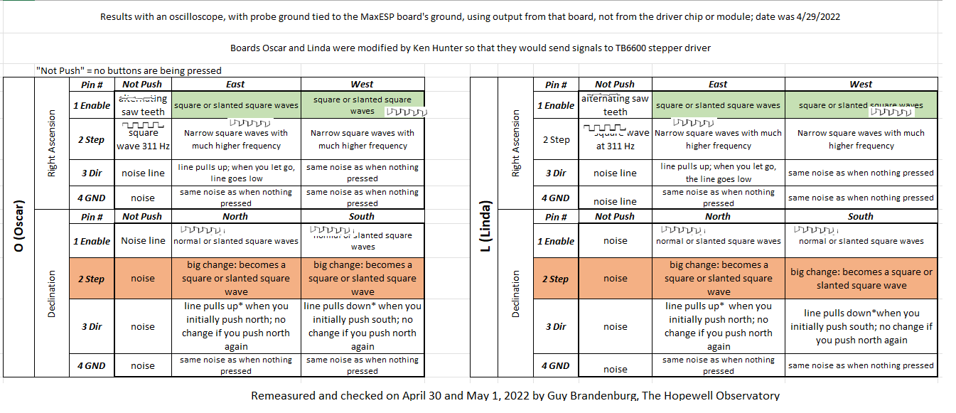
Our unmodified Arduino-based, green, MaxESP3.03 OnStep micro-controller unit board had two major errors: it didn’t put out any signal at all in the Enable channel in either Right Ascension or in Declination, and in Declination, the Step channel didn’t work either. (I can only guess what caused this, or when it happened, but these errors explain why we couldn’t get this particular board to work any more.)
We had the connecting wires between the two blue, modified boards of the same type and the external TB6600 stepper drivers in the wrong arrangement. We stumbled upon a better arrangement that Bob Benward had suggested, and indeed it worked!
I never would have figured this out without the nice hand-held digital oscilloscope belonging to Alan Tarica; his help and comittment to this project; advice from Ken Hunter that it was a bad idea to have the boards and stepper drivers connected, because the impedance of the motors makes the signal from the board too complicated, and also the signals to the motors themselves are extremely complex! Let me also thank Bob Benward for making beautiful and elegant schematics from the drawings I’m making with pencil and eraser on a couple of 11″x17″ sheets of stiff art paper and pointing out the anomalies between our (Ken’s? I thought I was faithfully copying his arrangements….) original wiring connections and what the manual recommends.
I’m puzzled that our earlier arrangement worked at all. Given that this oscilloscope sees extremely complex, though faint, voltage curves from my own body (anywhere!), I am guessing that electrical interference fooled the drivers into sending the correct commands to the stepper motors even though the STEP and the DIRECTION wires were crossed.
In any case, I attach tables summarizing what I found with the same oscilloscope I had in the previous post. I have highlighted parts that differ between the three boards. Boards “Oscar” and “Linda” are basically identical ones, both of them modified to bypass the location where small, internal stepper motor drivers (about the size of the last joint on your pinky finger) are normally held. Instead, these two boards, both blue in color, connect to two external black-and-green stepper drivers about the size of your hand.
Board “Nancy” differs from the other two in a number of ways: it’s green, which is not important for its function but makes it easier to distinguish. It is also an unmodified one, and it carries TMC5160 stepper driver chips pushed into two rails.
I used orange and green to highlight the differences in output.
With electronics: when it works, it’s amazing, but it is very, very fragile.
==========================
Edit: It all works just fine on my desk. I hope it will also work once we put it into the telescope’s cavities and wire everything up!