This time I attempted to detect a different transit of another star using two different setups on the grounds of Hopewell Observatory in northern Virginia.
A Canon 6D DSLR mounted on a big, heavy 14-inch Schmidt-Cassegrain telescope on a very sturdy AP1600GTO equatorial mount
An alt-az Seestar S50 all-in-one astro camera
Can you spot where the exoplanet TOI-1259-b dimmed the light from its host star?
(Hint: this is a trick question!)
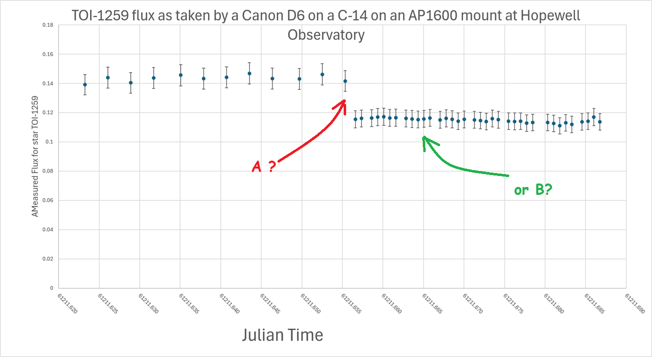
Here are the graphs I made from the data I collected:
Was it at A? Or did it happen at B? (Trick question!)
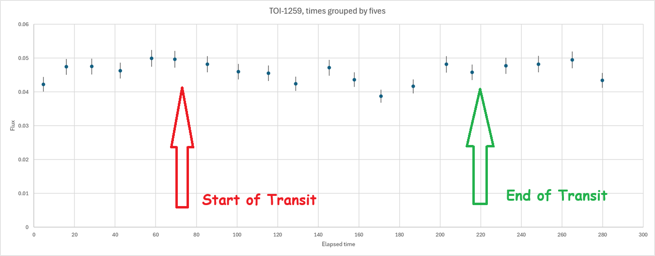
And this graph is what I got from my SeestarS50:
Psst:
Point A in the first graph was when I reduced the exposure time on the camera from 2 minutes to 30 seconds. That caused all of the fluxes to decrease, because cutting the time by 4 reduces the number of photons captured. Arrow B points to where the transit was supposed to happen, with a 2.7% decrease in brightness.
Do you see it?
Me neither.
In the second graph, done by the Seestar at the same location on the same night, smoothed as much as I can by averaging successive images, I again don’t see much evidence of a 2.7% dip in total flux.
Conclusion: chasing exoplanet transits looks like it could be easy, but it’s not.
===============
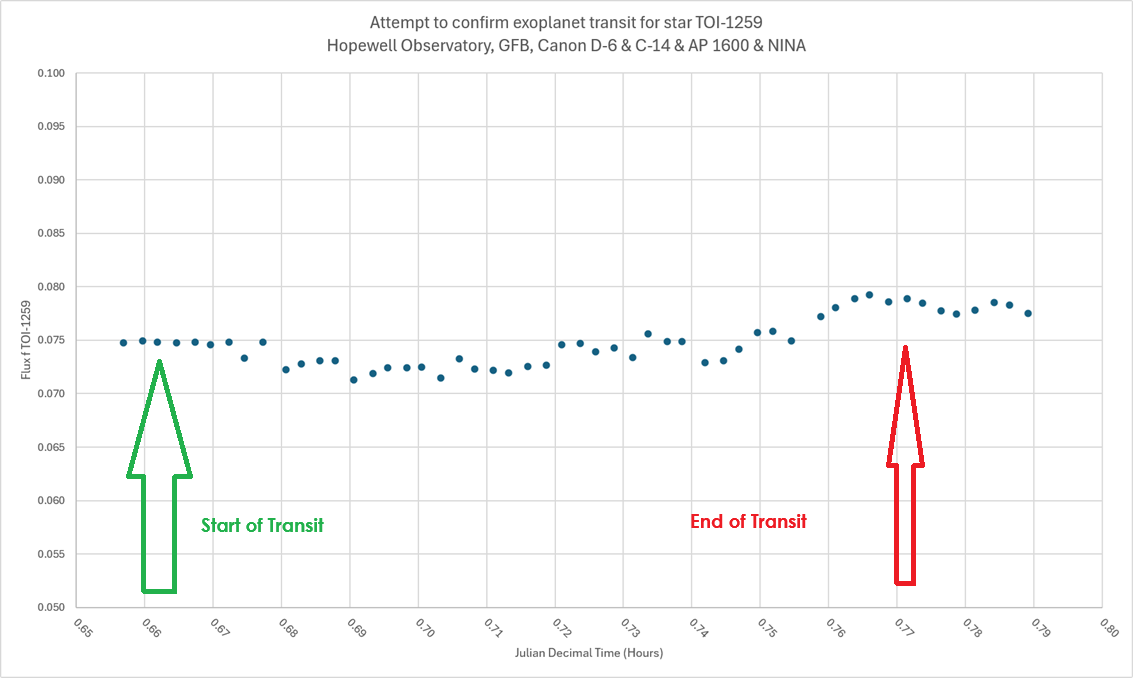
This graph here is no better.
And here is where I extracted just the two green channels:
No, I am not at all convinced that my measurements captured anything.
Do you see a transit in this data? I would say, “Maybe”.
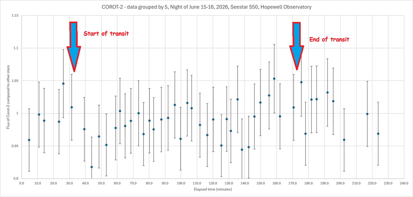
Since the Seestar has quite a bit of error, caused in part by its Bayer array of green, red, and blue pixels, I grouped my original measurements (processed in AstroImageJ) in groups of 5, using Excel to do so.
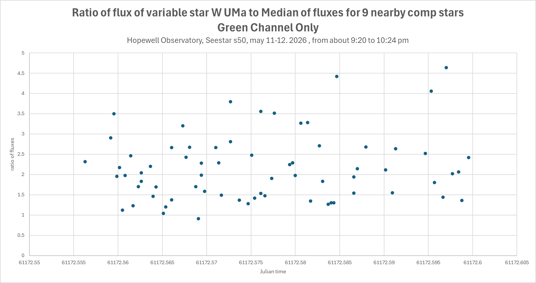
Latest results on a known variable star, W Ursae Majoris with my Seestar S50 during a very nice night: complete garbage. The graph below shows the flux of my star, WUMa, compared to the median of 9 comparison stars in the same frame, chosen by AstroImageJ.
As you can see, there is no real pattern.
If this data were real, then this star would be changing its brightness by a factor of three or for in less than a minute, with no discernable pattern. While a candle flame will flicker like that, it is simply not possible for something as large as a star to vary as quickly as that. In fact, this star is actually a contact-binary (double star) with a rotational period of about 8 hours. Even with the noise, I see no sign of a trend over these two hours.
The weather was very good, there was very little light pollution, and this star was quite high up in the sky the entire time, and none of the stars were saturated. But this data is just so, so noisy.
(I used ASTAP and AstroImageJ to do the plate solving and comparison of brightnesses. AIJ is an absolutely amazing program that automates so much of the tedium of this sort of process. For this graph, I had AIJ extract the green channel from the GRGB Bayer pattern, hoping that eliminating the blue channel would reduce atmospheric problems, but no luck so far. Combining all channels was no better.)
Other people claim success, but so far I’m zero for 12 in detecting exoplanet transits, and only 1 out of a dozen or so variable star measurements. Not sure what I am doing wrong or how I can reduce the errors. Yes, it’s true that this is only 2 hours out of an 8-hour period, but this data does not make any sense!
I’ve captured some variable stars, both with somebody figuratively holding my hand at almost every step of the way, 22 years ago, at a 2-week summer session at Mount Wilson that I highly recommend, and also with a Seestar S50, after failing a few times.
I was hoping to be able to finally capture an exoplanet transit. I tried in a couple of different ways on the night of January 18-19, but failed. Even so, I count the night as a major success.
It turned out that there were four (yes, 4!) different exoplanets that were supposed to have transits quite visible, during the same night, from my location (Hopewell Observatory in northern Virginia), and I was going to be staying up there all night anyway, with some others.
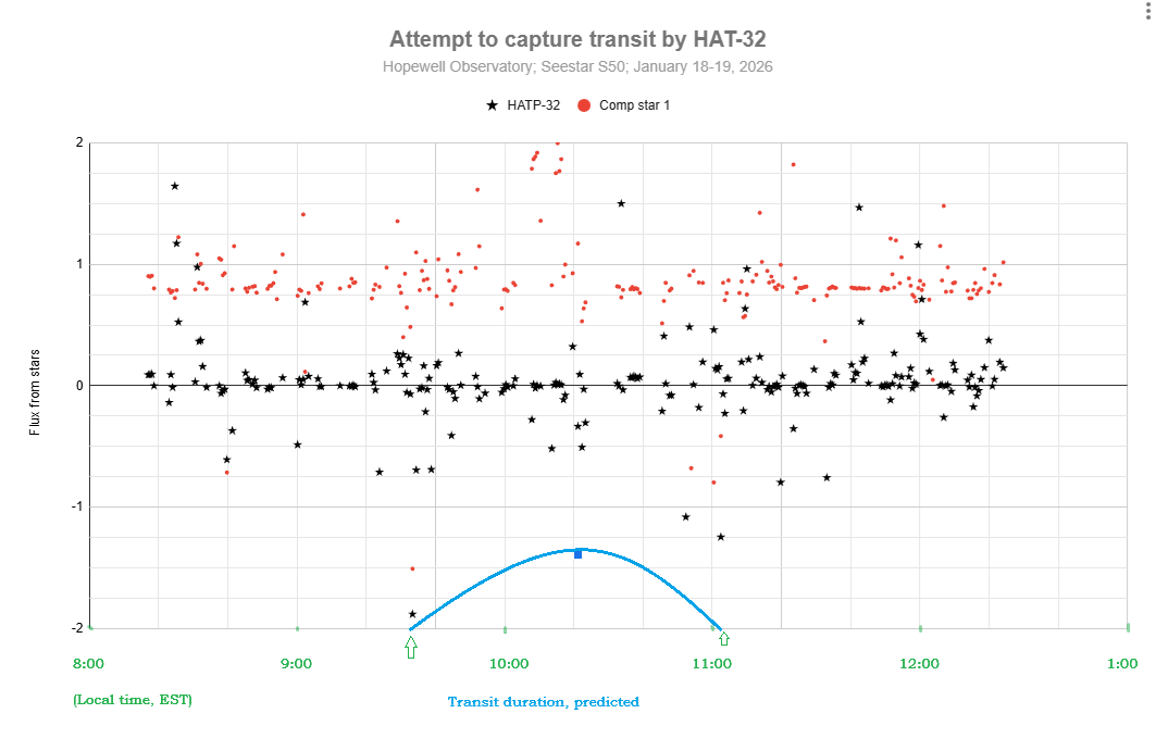
I used the Plan mode of my Seestar to take 30-second exposures of the star that looked like it would be the easiest to capture, namely HAT-P-32, which is in Andromeda at Right Ascension 02h 04m 10.00s and Declination +46° 41` 16.00″, It was supposed to have a depth of transit (or coverage of the star by the planet) of 22.2 parts per thousand, or 2.22%, which I thought sounded like quite a bit.
Unfortunately, it’s not very much at all, at least in terms of star magnitudes!
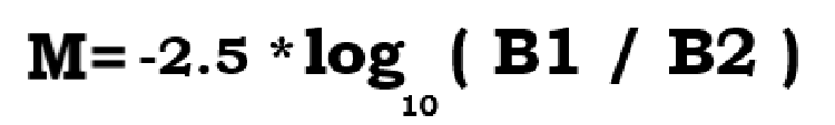
Perhaps you knew (I had forgotten it) the formula for turning brightness changes into magnitude changes.
(M is the magnitude change, B1 is the actual measured flux of photons at time 1 or from star 1, and B2 is the same flux, measured the same way, at time 2 or from star 2.)
You don’t even need to remember what a logarithm is to punch this into your calculator. I found that if you make it so that the ratio of B1 to B2 is one-half, you get a result of 0.75257… and if you try it the other way around, you get the exact same result, with a negative sign in front.
Let’s see: a drop in brightness of 22.2 parts per thousand leaves 977.8 parts per thousand still reaching my telescope. So my B1 needs to be 977.8 and B2 needs to be 1000. Or I could just type -2.5*log(0.9778) and when I do that, I get a drop in magnitude of 0.023, which is not very much at all!
Well, here is my attempt at detecting a transit for HAT-P-32b. I don’t see any sign of a transit. Do you? Part of the problem may have been that my target star was in the trees for part of the time…
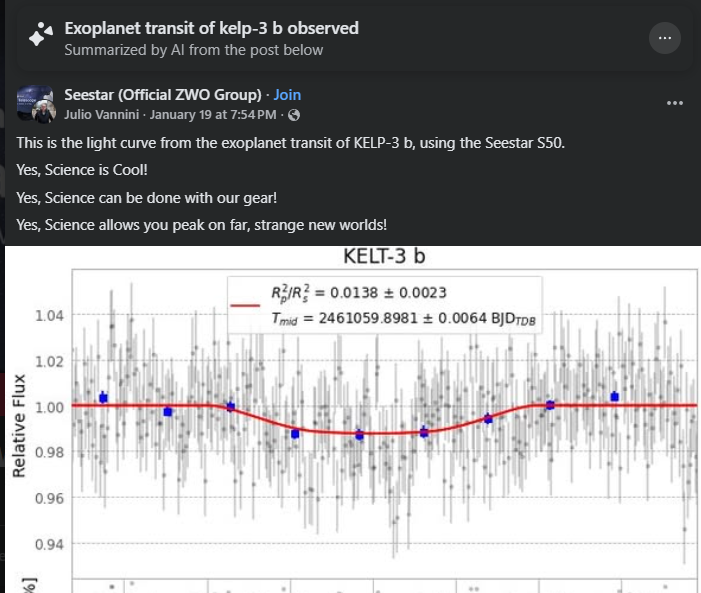
It appears that others have succeeded at this:
I will hope for better weather, better preparation of every step, and fewer tree branches next time!
By the way, here is my workflow. Steps 0 – 2 should be done at home, inside, in comfort, well before leaving for your observing site.
0. You must have both SeeStar and plate solving software (and its databases) operational on your computer. Download and install you have SeeStar, AstroImageJ, Astronometry.net and all of the databases for these accessible on your computer. You can also use ASTAP if you prefer for plate-solving, but AIJ uses Astronometry.net.
Look up which exoplanets are supposed to be visible in your area on the Swarthmore database, for how long, and in what part of the sky. Pick the best ones, with the greatest change in brightness. Print out the data.
2. Connect your Seestar to your tablet or smartphone and create a Plan to image that star for the entire time, with 30 second exposures, no filters, saving every frame. Double-check all your settings! You can do one target after the other, sequentially, but with the current SeeStar software, it doesn’t appear that you can ask it to rotate among several targets for a period of time. If you want to study variable stars, you might find that the Seestar’s pixel wells will get saturated with too many photons, which renders all your time and data is useless. To stop the saturation, set the exposures to as short as possible (10 second exposures), and set the light-pollution filter. If it’s still saturated, you might even need a sub -aperture mask to cut the signal further. You may or may not find that you have to manually change settings at various times during the night; if so, set an alarm for yourself.
3. Later, at the observing site, after sundown: Level your tripod, attach Seestar, turn it on, arrange for a power supply for it, use Bluetooth connect the same tablet or smartphone that you used to make the plan, and tell Seestar to start implementing your Plan. Check the clock and the smart device to make sure Seestar has actually started carrying out the plan. Periodically, re-check to make sure the images look decent. (I have found that Seestar is actually very good at centering your target precisely where you asked it to go to!
4. Let the Seestar do its thing. Check the image that shows up in ‘Star Gazing’ every so often. That window shows you the latest version of the stacked and calibrated image – which you won’t need for attempting to catch an exoplanet transit — not the current sub-exposure.
5. The next morning, in comfort, use a USB-C cable to connect your Seestar to a computer. Use a finder to locate the My Works folder on the Seestar, and find the folder that has all of your subs (frames). They should be in ASIF format. If you like, you can upload them to your computer, or else you can leave them on the Seestar. Take your pick.
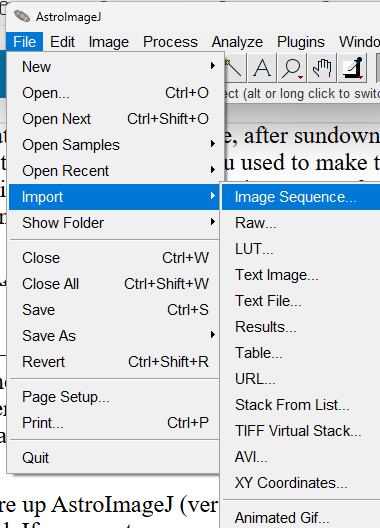
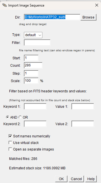
6. Fire up AstroImageJ (version 6) on your computer. Use File/Import Sequence to load that same sequence of subs that you just found. Keep in mind that some parts of the process (especially plate solving) might tie up your computer for a long time, perhaps hours. I would suggest only importing every 10th sub, to begin with, to find out if the whole stack of images is garbage or useful. If desired, you can always import the entire stack later. If I change the Step to 10, it will instead load image #1, then #11, then #21, and so on…
6. Inspect the images, and make a note of the ones you think are garbage. Get rid of those subs.
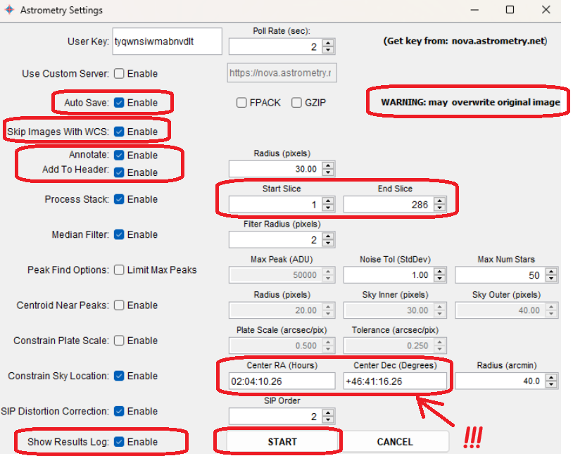
7. Then have AIJ do a plate-solve by chosing WCS (World Coordinate System) then Plate Solve with Astronometry.net (With Options). One of those options should be the coordinates of your star, which you should type in manually. You will need an Astronometry.net user key. You may use mine if you want: tyqwnsiwmabnvdlt. Make sure that Autosave and Skip Images With WCS are Enabled. When you have all that done, click on ‘Start’.
AIJ and Astrometry will then do their best to figure out exactly where the image was in the sky, and will record the RA and Dec of every single object in it and add that to the FITS header. AIJ&A will also indicate which are the cardinal directions. Hopefully, they will be able to solve every image. If Astrometry.net fails, you can try doing the same thing with ASTAP instead, which is insanely fast.
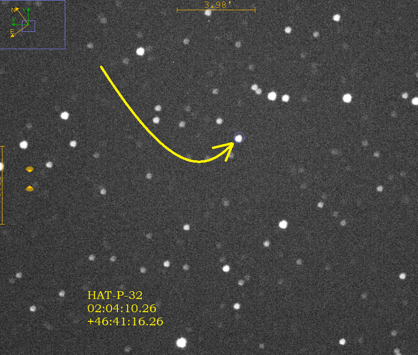
8. Once all of your images have been plate solved, then enlarge one of the images and find your star by checking the coordinates very carefully by moving your mouse around on the image. Since your image has been plate-solved, AIJ now knows exactly how to match the pixels on your screen to the coordinates in the sky, which is extremely impressive! (Try doing that yourself, by eye!) Pay attention to the ‘North” and “East” arrows. North is in the positive declination direction (degrees), and east is the positive right ascension direction (hours). Zoom in to your star, and then do a screen-snip and save it to some other app, and draw arrows showing exactly which star is the one you want, like I did here for my star, HAT-P-32. I also typed in its coordinates. This is for your own reference.
9. The next step is to have the computer compare the brightness of your selected star with a dozen or so comparison stars, and to do so in every frame (or ‘slice’ or ‘sub’), and show you the results in table (spreadsheet) form, and as a graph (chart) of the brightnesses over time of as many of the stars as you like. AIJ does this incredibly well, and incredibly quickly1 You don’t have to go frame by frame, measuring the brightness by eye of each and every single selected star, and noting any changes in brightness, by hand, as was done a century ago or so, in the days of photographic emulsions on thin glass plates. Here is a method for doing it in AIJ:
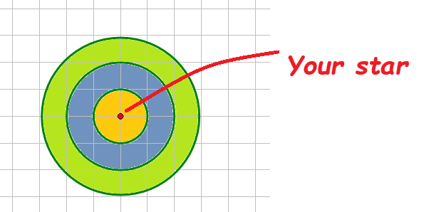
10. So what on earth is it doing, and how does it measure comparative brightness? My understanding is that it draws a three circles of increasing radii around each star, as I show here:
Basically, the software counts all the photons that it captures inside the first ring, which I labeled in yellow. It produces a number: the full width half max. Then it does the same thing for the photons in the outer ring, which it then assumes is the background brightness. I shaded this ring as olive green. It subtracts the FWHM for the yellow ring minus the FWHM of the green ring. It also compares those numbers for all of the comparison stars, and displays all the data in a variety of ways, including a spreadsheet and a graph.
11. Unfortunately, I found that I was unable to get AIJ to make very useful graphs, so I exported the entire spreadsheet into Excel and Google Sheets and made my graphs there.
Here is a link to a much better article on doing much the same thing:
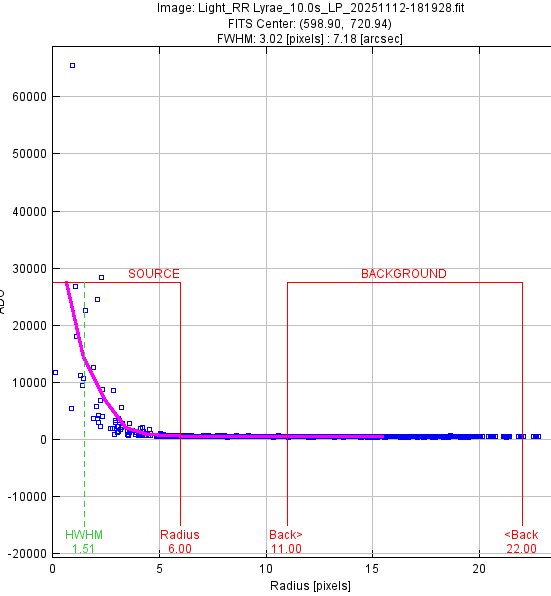
This graph gives me confidence that defocusing will solve my overflow problem. It’s a profile of the number of photons/electrons captured (vertical axis) versus the distance from what I thought was the exact center of the star RR Lyrae aka HD 182989.
(It is amazing how fast the computer works this out! I’m used to my middle school or high school students working things out like this by hand at first — it’s a very slow and tedious process! Let us give a tip of the hat to Williamina Fleming, who was the first person to notice and record that RR Lyrae was a variable star. She did so by examining glass plates on which were little dark spots made by stars’ light striking particles of suspended silver nitrate, without a blink comparator! Wow!)
Notice that there is one
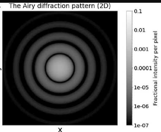
If I defocus the camera a bit, that saturated value would get spread out over an airy disk that might look like this:
I went up to Hopewell on Wednesday night, and practiced once again taking images of RRLyrae with my Seestar S50, but this time with the built-in light-pollution rejection filter in place. I figured that would reduce the number of photons by a lot, and maybe by enough to stop overwhelming the pixels.
Unfortunately, it was not sufficient, so, since I cannot reduce the number of seconds of exposure for each sub-image (or ‘slice’ as AstroImageJ calls them) below 10, and I cannot change the ISO or gain for the chip, the only choices left are, in order of ease of implementation:
De-focus the images to spread the photons into a wider range of pixels, hopefully not causing any of them to become saturated, but not so much as to confuse the plate-solving app;
Make a black, circular mask smaller than 50 mm in diameter and put it in front of the lens, reducing the total number of photons;
Persuade the engineers and programmers at ZWO to change the software to allow users to reduce the length of exposures, and to allow time lapse photography with what they call Star-Gazing but everybody else calls deep-space observing.
Number 1 I will do next time.
By the way, the exact mechanism by which this variable star dims and brightens is still not fully understood, though its timing cycle is extremely regular and quite well known.
No Auroras for me:
It was very cold and windy so I couldn’t stand being outside up on the Bull Run Mountain ridge for very long at a time. The sky was almost perfectly clear the entire night, and the beautiful winter constellations were extremely bright, and it was fun watching them make that apparent great pivot around us.
I saw no auroras; since I was was groggy (from forgetting my meds) and quite cold, so I spent most of the night inside napping and trying to get warm, but went out from time to time to look around and to check on the progress of my little Seestar. So when the peak happened I was probably dozing. Not too many other folks saw it, apparently, and the images I’ve seen were not nearly as impressive as for other aurorae on other dates. Oh, well.
As described in my last post, I got a light curve for a known variable star in my little Seestar S50 a few weeks ago that showed absolutely no variability whatsoever over a roughly 4 hour period. Since this star’s variation occurs extremely regularly, there is a known formula that will give you the precise location in its cycle if you feed in the Julian day (JD). I plugged the start and end times for my run, and got the following:
And was confused
So RRLyrae should have dropped from something near 7.3 magnitude to around 7.6 magnitude, which is a LOT for this sort of thing. But my graph of brightness of RRLyae, compared to a nearby star of roughly the same magnitude, looks like this:
Which is barely any change at all. The few pairs of dots below the blue blob line are glitchy data that should be ignored; notice that it happens for both stars. In fact, I see more variability in the pink comparison star’s brightness than I do with RRRLyrae.
Was the scope indeed pointed at the correct star? Well, I had plate solving on each and every frame, and they all agreed, so, yes.
I did notice a problem with saturation, but didn’t know exactly by how much. Nikolaos Bafitis suggested that I use my mouse to look more closely at the centers of the star images themselves in AstroImageJ. I did so, and at last noticed that one of the boxes held the number of pixel counts right under my mouse pointer. Duh! Sure enough, my target star, RR Lyrae, had a count of 65,533, which is 2^16, and (I looked it up) that is precisely the maximum for these pixels on these CMOS cameras. So that’s why RR Lyrae’s brightness was so steady: it was always OVERFLOWING.
So I have to figure out a way to gather fewer photons per pixel around the target and comparison stars. There are several possible ways of doing so without changing the electronics or trying to mess with the operating system or user interface.
Reduce the ISO setting from the current default value.
Shorten the exposure time.
Change the focal ratio by placing a circular mask over the lens aperture.
De-focus the images so that the light is spread out over a larger area.
Add some sort of filter.
Unfortunately right now, the Seestar doesn’t allow you to do either number 1 or number 2. It would be nice if ZWO engineers would add those capabilities in the ‘advanced’ menu,
Number 3 is quite doable. I happen to have on hand a large roll of black Kydex plastic and a set of Forstner bits to make nice holes with. But it this would require a fair amount of time and effort. It would also reduce the resolution of an already rather small 50mm lens.
Number 4 is more easily doable: turn off the autofocus feature and do some experimentation to find a good fixed de-focus point. However, if the stars are too fuzzy, then plate-solving becomes much harder and slower.
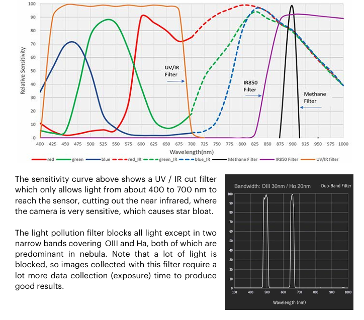
Number 5 can be done by using the built-in light pollution filter, whose transmission bandwidth is very small. It’s the bottom graphic below.
The graphics above come from an excellent Unofficial Seestar handbook written by Tom Harnish. He has a number of suggestions that I hope the engineers at ZWO pay attention to and follow.
The option that seems easiest is number 5, using the light pollution filter. If I couple that with the built-in time-lapse feature, I won’t fill the Seestar’s entire memory with a zillion FITS images.
I hope to try this tonight up at Hopewell Observatory, where I can set this up, have it run all night connected to mains power, and I can sleep in a nice warm cabin.
I’m still struggling to do simple astronometry even on a well-known variable star like RRLyrae. If you could measure its brightness for several nights without any breaks, you should in theory get a light curve like this:
I don’t. I’m still trying to figure out why my light curve for RRLyrae is so flat.
In 2004, during a two-week astronomy summer class at Mount Wilson, with a professional astronomer on hand guiding me at every step of the way over a couple of nights, I got light curves looking like pieces of the good example above. (Why only pieces? Because you can’t image a star in the daytime or when it’s cloudy or if the star is on the other side of our planet!)
A couple of weeks or so ago, inspired by an exoplanet light curve taken by a 9th grader with a Seestar, I had the opportunity to run my tiny automated Seestar S50 for 8 hours outside at Hopewell Observatory, which is a nice, safe location, connected to wall power. The weather was perfect for it. The scope is about the size of a large cookie tin on a tripod. It did nothing but take ten-second photos of a small region around RRLyrae from whenever stars came out until dawn.
Afterwards I then had to start analyzing those 972 images. My first step was to learn how to use YET ANOTHER astro-imaging package, called AstroImageJ. It’s quite impressive, but It pisses me off that every few years I have to learn an entirely new piece of software, and just throw out nearly everything I learned regarding anything software-related over the past 60 years!
I eventually figured out how to get AIJ to verify that the little scope was in fact looking at my chosen star — and it was.
I then asked AIJ to compare the brightness of RRLyrae to the brightness of five or six other stars of similar brightness that happened to be located in the same field of view, for each image. (Today’s computers quickly do all sorts of math on the values of certain pixels in certain rings around certain stars, at lightning speeds, but the human computer of 1899, Williamina Fleming, who discovered this star, had to do it completely manually by comparing the size of the spots on a glass photographic plate. My hat is off to you, Ms Fleming, and all the other unsung female computers!
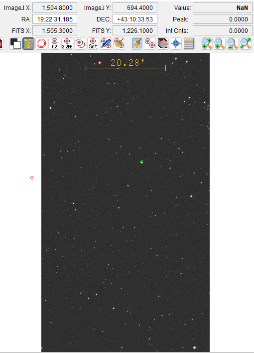
Here is a screenshot of the very last image in the series I took. The RA and Dec are the coordinates of RRLyrae, which AIJ has circled in green. The stars circled in red are comparison stars. That 20.28′ legend is in arc-minutes, 60 of which equal one degree. So the field of view is a bit over half a degree across and roughly a degree vertically.
To my surprise, my results were totally different from what I expected to find.
The blue dots are RRLyrae’s brightness on some scale that the computer cooked up, and the pink ones are from one of the known comparison stars. The x-axis goes from roughly 0.48 to 0.64, or 0.16, which is 1/6 of a day, or 4 hours.
The cases where both the blue and pink dots drop down below 1.0 are garbage caused by some glitch and should be ignored. But one thing is for sure: there is no sawtooth spike in my data for RRLyrae’s brightness during those 8 or 9 hours!
Four possible reasons are:
I’ve made a great scientific discovery! (probably not correct)
2. Wrong star? (I don’t think so. Checked and re-checked)
3. Perhaps those 8 hours happened to correspond to a flat place in the light curve (Possible — I just noticed that these images end before midnight, but I thought it kept working until dawn! Must re-check!)
4. The pixels all are too saturated, ie were exposed for too long,, which fills up the pixel with too many electrons. (This is possible, I guess, but each of these were merely 10 second-long exposures, which doesn’t sound very long to me, but maybe I’m missing something important).
Saturation is what the following graphic seems to indicate:
If it is indeed saturation that is making all the stars not change brightness, then what do I do?
I don’t think I can control the gain or ISO inside SeeStar, but I can ask for shorter time exposures, I think, by trying a time lapse and asking for shorter exposures, if possible. I just need to have time and a location to let it run all night without anybody disturbing it, making a time lapse of the sky.
Come to Bull Run Mountain for a free night under the stars looking at a variety of targets using the telescopes at the Hopewell Observatory on Saturday, October 26, 2024. If it’s cloudy, we will try again on the next evening, Sunday the 27th.
You are invited, but will need to RSVP and, in this litigious age, must agree to a waiver of liability for anything that might happen up there, like tripping over rocks and trees. The waiver also includes detailed driving directions.
But if you take the risk you can view, for free, Venus, Saturn and its rings, Jupiter and its moons, Uranus, Neptune, the current comet Atlas, the Milky Way, and a whole bunch of nebulae, galaxies, Messier objects, and beautiful double stars.
We suggest arriving near sundown, which will happen near 6:15 PM. It will get truly dark about an hour later. You can stay until midnight, if you like.
There are no street lights near our observatory, other than some dimly illuminated temporary signs we put along the path, so you will probably want to bring a flashlight of some sort. In the operations cabin we have a supply of red translucent plastic film and tape and rubber bands so that you can filter out everything but red wavelengths on your flashlight. This will help preserve everybody’s night vision.
Hopewell is located on the first ridge of the Appalachian mountain chain that you see as you drive west from the DC beltway, near Haymarket. Our elevation is about 1100 feet, and we have much less of a problem with dew than other observing spots in northern Virginia. The last two miles of road are dirt and gravel, and you will need to walk about 200 meters/yards from where you park. Some parts of the road are pretty rough, so don’t drive anything with low clearance underneath. Our parking spaces are pretty limited, so consider car-pooling if possible. Handicapped persons or telescopes can be dropped off at the observatory.
We do have electricity, and a heated cabin, but since we have no running water, we use bottled water, hand sanitizer, and a pretty nice outhouse. We will have the makings for tea, coffee, and hot cocoa in that cabin.
If you like, you can bring a picnic dinner and a blanket or folding chairs, and/or your own telescope or binoculars, if you own one and feel like bringing them. We have outside 120VAC power, if you need it for your telescope drive.
At this time of year, the bothersome insects have mostly gone dormant, but feel free to use your favorite bug repellent, (we have some). Remember to check yourself for ticks after you get home.
We have a variety of permanently-mounted and portable telescopes of different designs, some commercial and some made by us. Two of our telescope mounts are permanently installed in the observatory under a roll-off roof. One of the mounts is a high-end Astro-Physics mount with a 14” Schmidt-Cassegrain and a 5” triplet refractor. The other mount was manufactured about 50 years ago by a firm called Ealing, but the motors and guidance system were recently completely re-done by us with modern electronics using a system called OnStep. We didn’t spend much cash on it, but it took us almost a year to solve a bunch of mysteries of involving integrated circuits, soldering, torque, gearing, currents, voltages, resistors, transistors, stepper drivers, and much else. We could not have completed this build without a lot of help from Arlen Raasch, Prasad Agrahar, Ken Hunter, and the online “OnStep” community.
We also have two home-made Dobsonian telescopes (10″ and 14″ apertures) that we roll out onto our lawn, and have been lent a pair of big binoculars on a parallelogram mount.
The location of the observatory is approximately latitude 38°52’12″N, longitude 77°41’54″W.
Click here for the RSVP form to get detailed directions. You must sign the waiver to visit. If we cancel on Saturday the 26th because of bad weather, we will notify you by email and will try again on Sunday the 27th.
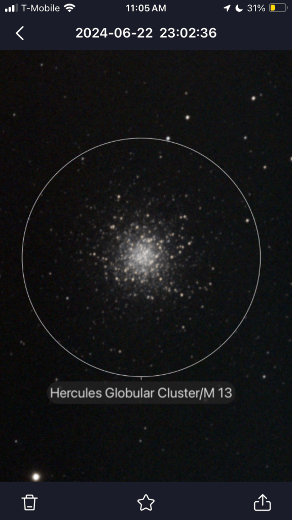
Look what this little thing can do that I’ve always failed at myself, even with an entire observatory at my disposal: take decent astrophotos.
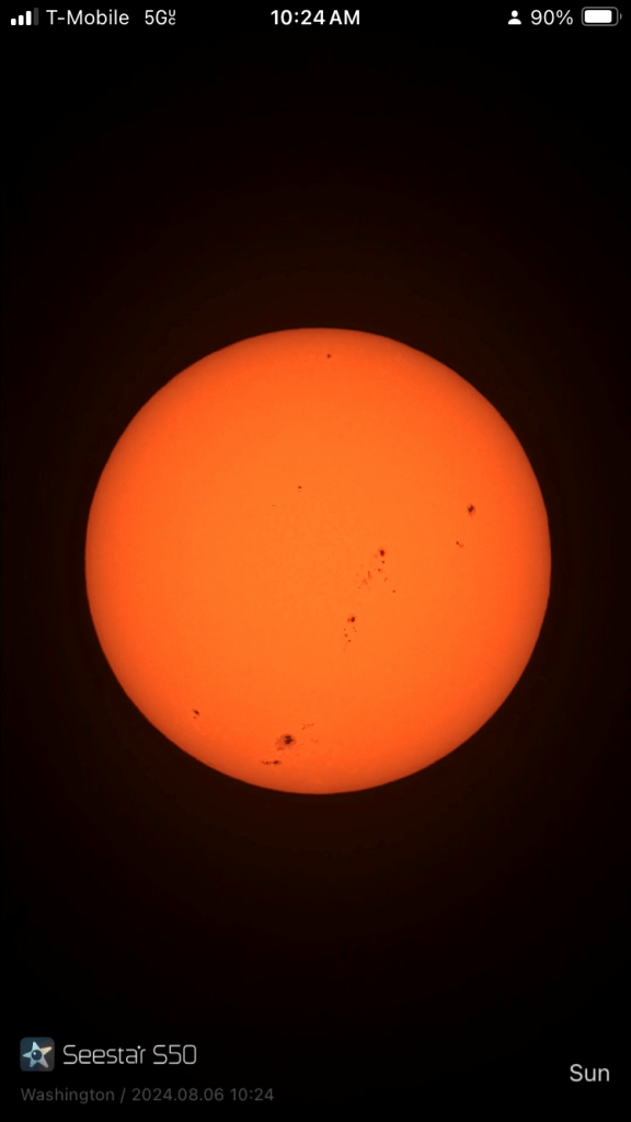
Here it is on a home made tripod, taking photos of the sun. Notice the reflective solar filter. Here are two images:
The device woke up, and after less than a minute of self’s-calibration, it pointed very accurately at the sun and focused itself perfectly. It produces a continuous feed; I even did 100 frames of a time-lapse. It’s all stored on my cell phone but I can share the photos or even live views with folks nearby.
And from night time spots here in DC and NOVA:
This can take tolerable astrophotos even when surrounded by streetlights!