• My series on making a Newtonian telescope
  • How Leon Foucault Made Telescopes

Guy's Math & Astro Blog

Guy's Math & Astro Blog

Category Archives: History

The Mathematics of George Washington

24 Friday Feb 2017

Posted by gfbrandenburg in History, Math, Uncategorized

≈ 2 Comments

Tags

George Washington, History, Math, surveying

I recently learned some things about how the young George Washington did math, including surveying. Mathematician and historian V. Frederick  Rickey gave a talk 2 nights ago at the Mathematical Association of America here in DC, based on his study of GW’s “cypher books”, and I’d like to share a few things I learned.

(1) The young George appears to have used no trigonometry at all when finding areas of plots of land that he surveyed. Instead, he would ‘plat’ it very carefully, on paper, making an accurate scale drawing with the correct angles and lengths, and then would divide it up into triangles on the paper. To find the areas of those triangles, he would use some sort of a right-angle device, found and drew the altitude, and then multiplied half the base times the height (or altitude). No law of cosines or sines as we teach students today.

(2) He was given formulas for the volumes of spheroids and barrels, apparently without any derivation or justification that they were correct, to hold so many gallons of wine or of beer. (You probably wouldn’t guess that you had to leave extra room for the ‘head’ on the beer.) Rickey has not found the original source for those formulas, but using calculus and the identity pi = 22/7, he showed that they were absolutely correct.

(3) GW was a very early adopter of decimals in America.

(4 ) This last one puzzled me quite a bit. It’s supposed to be a protractor, but it only gives approximations to those angles. The results are within 1 degree, which I guess might be OK for some uses. I used the law of cosines to convince myself that they were almost all a little off. Here’s an accurate diagram, with angle measurements, that I made with Geometer’s Sketchpad.

His method was to lay out on paper a segment 60 units long (OB) and then to construct a sixth-of-a-circle with center B, passing through O and G (in green). Then he drew five more arcs, each with its center at O, going through the poitns marked as 10, 20, 30, 40, and 50 units from O. The claim is then that angle ABO would be 10 degrees. It’s not. It’s only 9.56 degrees.

george-washingtons-protractor

A Talk at AHSP on Telescope Making

16 Friday Sep 2016

Posted by gfbrandenburg in astronomy, History, Telescope Making

≈ Leave a comment

Tags

AHSP, Almost Heaven Star Party, Charles Messier, Messier Objects, NOVAC, Spruce Knob, West Virginia

Two weeks ago was the Almost Heaven Star Party on the slopes of Spruce Knob, West Virginia, sponsored and organized by the Northern Virginia Astronomy Club (NOVAC). The weather was wonderful, and we could see the Milky Way and lots of Messier objects with our naked eyes, every single night for four nights. This is by far the longest stretch of good weather I’ve ever experienced up there at The Mountain Institute.

(Friday and Saturday, it was only clear for a few hours, but Sunday and Monday nights were clear all night, AND there was NO DEW to speak of!! Wow!!)

During the daytime, there were lots of talks and also activities and expeditions such as hiking, spelunking, visiting the National Radio Astronomy Observatory at Green Bank, canoeing, and Phun With Physics and arts & crafts for kids. I particularly enjoyed the talks on Russell Porter (the founder of amateur telescope making in the US and one of the major designers of the 200-inch telescope at Palomar), LIGO (detection of gravity waves), and Rod Molisse’s talk on 50 years of mostly-commercial telescopes as seen in the pages of various astronomy regime.

I was one of the speakers and gave a little talk on telescope-making. If you care to sit through it, you can find it along with all of the other talks (many of which I missed for various reasons) at this web-page.

I brought my home-made 12.5″ Dob-Newt [shown to the left in the picture below] and added about a dozen items to my formal list of Messier objects. (I had already seen all 100+ objects, but hadn’t recorded enough details on them to be able to earn one of the ‘merit badge’ pins from the Astronomical League, so I’m going through the list again

.img_0198

(If you didn’t know: Charles Messier loved hunting comets about 220 years ago, with what we would consider today to be a fairly small (4″ diameter) refractor that he used from downtown Paris, not far from where I lived back in 1959. Comets look like fuzzy patches in the sky, and so do galaxies, star clusters, and illuminated clouds of gas, all of which are MUCH farther away and MUCH larger. Comets are part of our own solar system, and move noticeably from one night to the next against the apparently fixed background of stars. Messier is credited with discovering 13 comets. But when he discovered a fuzzy item in the sky that did NOT move, he would record its location and its appearance, so as to avoid looking at it again. He published and updated this list a few times before he died, 199 years ago. Nowadays, his list of things-to-be-avoided are some of the most amazing and beautiful things you can see in the night sky. I’ve tried imaging a few of them, but am very, very far from being proficient at it. I attach my best one so far, of something called the Dumbbell Nebula. No, it’s not named after me. And thanks to Mike Laugherty for helping with the color balance!)

dumbbell-processed-november-1-2015

Movie about Ramanujan

19 Thursday May 2016

Posted by gfbrandenburg in History, Math

≈ Leave a comment

Tags

ramanujan

I recommend going to see ‘The Man Who Knew Infinity’, about the famous Indian mathematician Srinivasa Ramanujan, whose originality astonished the greatest mathematicians of his day, G H Hardy and Littlewood.

It’s a historical romance rather than a documentary, so there are parts that are completely made up — like German Zeppelins bombing Cambridge University during World War 1, and off-duty British soldiers beating up Ramanujan for being a foreign draft dodger. A weird aspect is that the actors and directors don’t seem to be on the same page about the correct pronunciation of Ramanujan’s name. They mostly put the accent on the third syllable, where as far as I can tell it should be more like ruh – MAHN – uh – jahn.

However, there was such a bombing near-by during the war, and the British army did have temporary hospitals for wounded soldiers during that war, and Ramanujan did contract tuberculosis and die at the sadly early age of 32, after he had gone back home. And apparently his mother had indeed been intercepting letters to and from his wife, so they were completely cut off from each other, as the movie states.

And of course, they can’t really explain much of the mathematics – heck, I can’t understand much of anything that Ramanujan did! Even his simplest formulas are way, way over my head! Dramatizing partitions of a number was probably a wise move, since it’s one of the few things that an ordinary person might understand.


On Making an Artificial Star for an Indoor Star Tester

04 Sunday Jan 2015

Posted by gfbrandenburg in History, Telescope Making

≈ 2 Comments

Tags

artificial star, ATM, CCCC, couder, foucault, Hubble, NCA, Ronchi, star testing, Telescope

I help run the amateur telescope-making workshop at the Chevy Chase Community Center in Washington, DC, sponsored and under the auspices of the National Capital Astronomers. Both the NCA and its ATM group have been on-going since the 1930’s, well before I was born. In our ATM group, have the somewhat esoteric thrill of manufacturing incredibly accurate scientific devices (telescopes), from scratch, with not much more than our bare hands and a few tools. And then we go and use them to observe the incredible universe we come from.

Since these telescope mirrors are required to be insanely accurate, we need extremely high-precision ways of testing them. However, we don’t have the tens or hundreds of thousands of dollars needed to purchase something like a professional Zygo Interferometer, so we use much cheaper ways of testing our mirror surfaces.

Some of those methods are associated with the names Foucault, Couder, Bath, Ronchi, Ross, Everest, and Mobsby, or are described with words like “knife-edge”, “double-pass” and “wire”. They all require some relatively simple apparatus and skill and practice in measurement and observation.

We are of the opinion that no one single test should be trusted: it’s easy to make some sort of error. (I’ve made plenty.) You may perhaps recall the disaster that happened when the Hubble Space Telescope mirror passed one test with flying colors, and other tests that weren’t so good were ignored. When the HST finally flew in orbit, it was discovered that the mirror was seriously messed up: the test that was trusted was flawed, so the mirror was also flawed.

We don’t want to do that. So, at a minimum, we do the Ronchi and Foucault/Couder knife-edge tests before we say that a mirror is ready to coat.

But the ultimate test of an entire telescope is the star test.

In principle, all you need for that is a steady star, your telescope, a short-focal-length eyepiece, and a copy of Richard Suiter’s book on star-testing optical telescopes.

Unfortunately, around here, it’s often cloudy at night, and if it’s clear, it might be windy, and around the CCCC building there are lots of lights — all of which make star-testing a scope on the two evenings a week that we are open, virtually impossible. We aren’t open in the daytime, and even if we were, I don’t see any ceramic insulators on any telephone poles that are both small enough and far enough away to use as artificial stars in the manner that Suiter describes. (There are a few radio towers visible, but I doubt that their owners would let us climb up one of them and hang up a Christmas tree ornament near the top!)

So, that means we need to make an artificial star.

I’ve been reading a few websites written by folks who have done just that, and it seems to be a bit easier than I thought. The key is to get a source of light that acts like a star at astronomical distances — but close enough that we can fit it inside the basement of the CCCC, probably not in the woodshop where we make the scopes, but more likely out in the hallway or in the large activity room next door, both of which are about 40 or 50 feet long.

So here are my preliminary calculations.

First off, it appears that the resolving power of a telescope equals the wavelength being used, divided by the diameter of the objective lens or mirror, both expressed in the same units. The result is in radians, which you can then turn into degrees, arc-minutes, arc-seconds, or whatever you like, but it’s perhaps easier to leave in radians. In any case, the larger the diameter, the tinier the angle that your telescope can resolve if it’s working properly.

I am going to use a 16-inch mirror diameter, or about 0.4 meters, as an example, and I will use green light at about 560 nanometers (560 x 10^-9 m) because that’s pretty close to the green mercury line we have in our monochromatic light box. I then get that the resolution is 1.4×10^-6 radians.

resolution of lens or mirror

(We can convert that into arc-seconds by multiply that by 180 degrees per PI radians  and by 60 arc-minutes per degree  and by 60 arc-seconds per arc-minute; we then get about 0.289 arc-seconds. If we were to use an 8-inch mirror, the resolution would be half as good, meaning the object would need to be twice as big to be resolved, or about 0.578 arc-seconds.)

resolution in arc seconds

I read that one can make an artificial star by using an ordinary eyepiece and a small illuminated hole that is put some distance away from the eyepiece. The entire setup is aimed at the telescope, and then you have an artificial star. Here is the general idea:

artificial star setup

Supposedly, the equations go as follows, with all of the dimensions in the same units. I think I will use millimeters.

Star Size of artificial rigWe want to make it so that the size of the artificial star will be small enough to be below the limit of resolution of any telescope we are making. I am pretty sure that we can set things up so that there is 40 feet (13 meters) between our telescope rig and the table or tripod on which we sill set up this artificial star.

I also know that I can find an eyepiece with a focal length of 12 mm that I’m willing to use for this purpose, and I also purchased some tiny little holes from “Hubble Optics” that are of the following sizes: 50, 100, 150, 200, and 250 microns, or millionths of a meter. Those holes are TINY!!! So that takes care of H and F. I still need to figure out what SS should be.

A few lines ago, I found that for a 16-inch telescope, I need a resolution of about 1.4×10^-6 radians. The nice thing about radians is that if you want to find the length of the arc at a certain radius, you don’t need to do any conversions at all: the length of the arc is simply the angle (expressed in radians) times the length of the radius, as shown here:

angle arc radius

c=theta times Radius

So if our artificial star is going to be 13 meters away, and we know that the largest angle allowed is roughly 1.4×10^-6 radians, I just multiply and I get 1.82×10^-5 meters, or 1.82 x 10^-2 millimeters, or 18.2 microns.

Which means that I already have holes that are NOT small enough: the 150-micron holes are about 10 times too big at a distance of 13 meters, so my premature rejoicing of a few minutes ago, was, in fact, wrong.  So, when I make the artificial star gizmo, I’ll need to figure out how to make the ‘star size’ to be roughly one-tenth the size of the holes in the Hubble Optics micro-hole flashlight.

Or, if I rearrange the equation with the L, H, F and SS, I get that L = H * F / SS. The only unknown is L, the distance between the hole and the eyepiece/lens. For H, I have several choices (50, 100, 150, 200 and 250 microns), SS is now known to be 18 microns or so (36 if I want to test an 8-incher), and I plan on using a 12.5 mm eyepiece. If I plug in the 150 micron hole, then I get that L needs to be about 104 millimeters, or only about 4 inches. Note that the longer L is, the smaller the artificial star becomes. Also, if I replace the 12.5 mm eyepiece with a shorter one, then the artificial star will become smaller; similarly, the smaller the Hubble Optics hole, the smaller the artificial star. This all sounds quite doable indeed.

Build Your Telescope Tube and Mount

16 Tuesday Dec 2014

Posted by gfbrandenburg in History, Telescope Making

≈ Leave a comment

Tags

alt-az, company 7, equatorial, hands-on-optics, plywood, teflon

7. Build the scope

A. There are many, many books and articles and websites devoted to the many, many ways of building your telescope tube and mount. We have quite a few of these books in our library, and you should definitely study them! In addition, public star parties put on by NOVAC, NCA and other local clubs often have home-made telescopes on the field, and you can ask the makers of those scopes how they did it. Fortunately for us, John Dobson came up with an excellent way of making inexpensive, easy-to-build and easy-to-use telescopes of the Newtonian model, even if he was a nut-case. Willmann-Bell publishes quite a few such books.

B. I strongly recommend an alt-az telescope mount for visual use, rather than an equatorial mount on a pier made of plumbing parts, as people used to make in the 1940s through the 1990s. (As noted earlier, if you want to do astrophotography, you will need a much more complicated and much more expensive mount that tracks the stars precisely. Building such a mount yourself is exceedingly difficult and requires precision machining and electronics!) Most important: plan to make a telescope that is easy to use and not too complicated to build! Using slight modifications of existing plans is much easier than trying something completely novel in design. If you strive for originality, you can be sure that you will need to modify and re-build parts of your invention, perhaps several times, because of problems that you didn’t consider or notice originally. (Think about what a nightmare it would be to drive a Model-T Ford automobile, the first real mass-production car, with all of its nutty and dangerous defects, compared to the comfortable and safe and reliable car that people drive today!)

C. I have a set of plans for a simple 6” Dob on this very blog. (Click for link)

D. At the CCCC, we also have a fairly decent set of hand and power tools for working with wood and metal, so you can make the rest of the telescope here if you like. Be careful, and follow safety directions!

E. We even have a wonderful assortment of ‘oops’ paints from hardware and paint stores, if you don’t mind the ghastly colors.

F. You will need at least half of a sheet of 4’ by 8’ plywood for the scope. The plywood can be any type you like, but don’t get a sheet that is warped or wet or too thin. Nice plywood like Appleply or Baltic Birch can be expensive, but it is strong and looks quite beautiful when varnished. Three-quarter inch thickness is standard, but it’s generally sold as a weird number like 23/32”.

G. You will also need the following commercially available items, some of which we usually have on hand, marked by “UOH”.

  1. Diagonal secondary flat elliptical mirror (we have a few)
  2. Secondary mirror holder
  3. Spider
  4. Focuser
  5. Eyepieces
  6. Finder scope(s) (I recommend a 1-power finder like a Telrad or a Red Dot finder, as well as another finder scope that magnifies about 5 to 10 times)
  7. Possibly a Barlow
  8. A few pieces of Teflon UOH
  9. A few square feet of Formica or the equivalent UOH
  10. Miscellaneous screws, nuts, bolts, screws, glue UOH
  11. Guidance UOH
  12. Paint UOH
  13. Random wood scraps, including a short 2-by-4 UOH
  14. For the mirror holder, you need: Three compression springs; 3 flat-headed machine screws; 9 washers; 3 wingnuts; and a small fresh tube of pure-silicone caulk or aquarium cement

H. We are very fortunate to have a local specialty store that sells telescopes and accessories to the public, called Company 7 . It’s located near Laurel, MD and has an amazing display of rare telescopes. Please shop there! (In other words, don’t talk their ears off getting their advice, and then order an item online because it’s a few dollars cheaper!)

(Link forward to the next section ==>)

(<==Link back to the previous section)

Figuring (parabolizing) Your Mirror

16 Tuesday Dec 2014

Posted by gfbrandenburg in History, Telescope Making

≈ Leave a comment

Tags

couder, foucault, parabolization, testing

5. Figuring and Testing

 A. Polishing pads do a great job of polishing out the pits, but they tend to leave a rough surface that is not a true paraboloid or even a section of a sphere, unless you are very, very lucky. Most folks will switch to a pitch lap for the figuring process, which involves removing sub-microscopic amounts of glass from various zones on your mirror, in order first to make it into a section of a sphere, and then into the bottom of a paraboloid – the only geometric figure that will reflect all of the rays that come from distant stars onto a single focal point. Many treatises have been written about figuring, and I’m not going to add to that list. “Understanding Foucault” by David Harbour gives an excellent explanation of the figuring process, as does Mel Bartels here. However, here are some of the basics:

B. You will need a pitch lap, made either of Gugolz or Acculap or Tempered Burgundy pitch. The first two are synthetic products whose composition is probably secret; the third one is made from the sap of coniferous trees. I’m not going to describe the process of making a pitch lap here, but I combine some of the methods of Carl Zambuto and John Dobson when I make a new one; you can watch it as we do it for you. It’s much less work if you can use a pitch lap that was made by or for someone else who has finished their own project. Sometimes a previously-used pitch lap will have sat around too long and might need to be scraped off and remelted. We generally use roughly square facets, which allow the pitch to flow better and conform itself to your mirror. Without the facets, any high points on the lap have a hard time being lowered. We also tend to use netting or a single-edge razor blade to make minifacets, which further help the lap to conform to the mirror.

C. Pitch is weird stuff. When it’s warm, it flows and it’s very sticky. When it’s cold, it is fairly hard, and you can shatter it with a hammer. If you leave a pencil or a coin on a pitch lap overnight, the next day you can see all of the details of the pencil or coin reproduced perfectly in the pitch. We want the lap to conform itself to your mirror. Then we use the pitch lap to remove all of the irregularities that were left by the polishing pads. So, we warm up the pitch lap to soften it a bit (using a heat lamp or hot water), spread Cerox or rouge onto your mirror, and then press the two together briefly but firmly. We often use some netting to create micro-facets, which help the pitch conform to your mirror even more.

D. The figuring stage can severely try your patience, especially if the tests show a surface that looks weird. But relax! If you persevere and don’t drop the mirror on the ground, success is guaranteed, since it’s just a matter of removing the correct millionth of an inch or two (much less than a micrometer) of glass from the correct zonal ring to achieve near-perfection. One needs to make sure that the lap actually conforms to the mirror; bad contact between the two can cause trouble, and so can a pitch lap that is too hard, too soft, or too thin. All of those are fairly easily fixed, with remarkable results. And we are here to help.

E. One major problem that can affect mirrors is a Turned-Down Edge (TDE). Opinions vary on what causes this dreaded condition, but the evidence suggests to me that TDE appears when the lap is exactly the same size, or slightly smaller, than the mirror itself. To avoid a TDE, do not chip off the parts of the pitch lap that ‘mushroom’ out past the edge. Let them stay there.

F. You will be instructed in a specific set of strokes which will first make your mirror into a sphere. Then, you will be instructed in a different set of strokes that will make your mirror into a good approximation of a perfect paraboloid. Texereau, LeCleire, and many other books describe those strokes. So did Leon Foucault in his 1859 article, which you can find on this blog/website. In our workshop, we will test your mirror frequently with a combination of tests, many of them invented by Foucault but later modified.

G. A very fast qualitative test is the Ronchi test, which you can look up. It gives you almost instant feedback on the presence or absence of bad features like turned-down edge (TDE), zonal defects (high or low rings), astigmatism (lack of symmetry), roughness, and so on. It will tell you whether your mirror is a sphere or not – if the Ronchi lines are perfectly straight, then you have a sphere. If they are not straight, then the test can tell us if your mirror is on the way towards being an ellipsoid with the long axis perpendicular to the mirror (or parallel to it), or a hyperboloid, or your goal, a paraboloid. There are several computer programs that provide simulations of what a perfect mirror should look like under the Ronchi test, but I’ve found you can’t always trust those simulations. RonWin is one such program, and Mel Bartels has another on one of his web pages.

H. A more time-consuming test that I find is necessary is the Foucault test as modified by Andre Couder, also known as the numerical knife-edge test with zones. If the Ronchigram looks good, and the numbers in the knife-edge zonal test are also within acceptable limits, then the mirror is done. A slight modification of this test is known as the Wire Test, which works well on fast mirrors. David Harbour’s article does an excellent job of explaining this test. One can use a pinstick method for marking the zones, or one could write directly on the mirror with a Sharpie, but we use a version that uses cardboard masks with holes cut out at carefully-measured zones.

I. We have tried a number of other tests, such as the double-pass autocollimation test, the Mobsby Null test, and the Bath Interferometer test, and have had difficulties getting good results with them. Therefore, we are continuing to use the Ronchi and Knife-Edge Zonal tests.

J. However, the best test of any mirror is the Star Test, which is the subject of an entire book by Richard Suiter. Some do this in the daylight, using sunlight reflected from very distant insulators on electrical poles. Most do it at night, but it requires steady air (‘good seeing’) and a clear sky as well. The Star Test is much easier to perform if the mirror is already aluminized and in a working telescope, which brings us to….

(Link forward to next section==>)

(<==Link back to previous section)

Rough Grinding of a Telescope Mirror

15 Monday Dec 2014

Posted by gfbrandenburg in History, Telescope Making

≈ Leave a comment

Tags

Hogging, Rough Grinding

(Part two of my description of the essential steps in making a telescope)

essential atm steps calculate sagitta

2. Hogging Out means making your mirror blank have roughly the proper concave shape for the focal length or f-ratio that you want. There are many articles and web pages on this, which you really should look at!

 A. The math is important: you want your mirror to be a parabola, and the equation for the depth (or sagitta) that you must grind into the glass isn’t too difficult. First of all, “f-ratio” means the ratio between the focal length and the diameter of the primary mirror. So if you plan on making an 8” diameter mirror with a 40-inch focal length, 40” divided by 8” gives you an f-ratio of 5. With no units. If you wanted a 10” diameter mirror with the exact same focal length, we would call that f/4. For the sagitta (depth of curve) required, it’s easiest to use the formula for a parabola facing upwards with its vertex at the origin, namely,  . and you will need to do a little math[1]. Here’s a diagram that I hope will help:  It is supposed to show a mirror (blue) with an insanely short focal length of 7.03 inches and a diameter of 10 inches. The sagitta is the depth at the center of the curve, or length CB, which will be the same as DE and GF. Using the formula   , and plugging in 5 for x and 7.03 for F, we get that y (the sagitta) would be about 0.889 inches, a bit more than 7/8” of an inch of glass to remove. And that’s what we see in the diagram, too, if you look carefully. For a more realistic example, let’s suppose we wanted to make a ten-inch mirror with a focal length of 60 inches (which means that the scope would be about 5 feet long, or roughly 1.5 meters). In that case, we would get a sagitta of about 0.104”, a bit more than a tenth of an inch. You will need some way of measuring the sagitta. We use some spherometers that we fabricated from bits of metal and various dial indicators. Some people use a collection of automobile mechanic’s feeler gauges and a straightedge that goes across the entire diameter. Note that a spherometer will typically NOT measure the entire diameter of your mirror, so you need to account for that smaller diameter. You should calculate and record what your numerical goal is for your chosen method of measurement. However: one nice thing about Newtonian reflectors is that the exact focal length isn’t very important – unlike the other telescope designs, where any deviation from the designed model will cause the project to fail catastrophically. A 6” f/8 scope will work just as well as a 6” f/8.15 scope or a 6” f/7.7 scope; the only difference will be that the first scope tube will be about 48 inches long, the second one closer to 49 inches and the last one closer to 46 inches long.

 B, To grind the mirror, we use relatively coarse grit (silicon carbide, which is not toxic at all) mixed with ordinary tap water. The water acts as a lubricant and also to keep down the glass dust – silica dust causes very serious lung problems if it’s dry. So we keep it wet. We begin with either 50, 60, or 80 grit, depending on the size of the mirror. We put the tool (another cylindrical piece of glass or ceramic, or else something we cast from dental plaster and hard ceramic tiles) on many thicknesses of clean newspaper, on top of the workbench. We dampen the newspaper so they won’t slide around. We sprinkle some water onto the tool, and spread it around with a finger. Then we sprinkle some grit onto the water and tool as if we were liberally salting a dish we were cooking or eating. Then using both hands, we carefully place the mirror face down on top of the tool. We use both hands to make the mirror travel in a circular path in either direction for about 6 turns, grinding the center of the mirror mostly against the edge of the tool. (This needs to be demonstrated!) Wide strokes are good, but the center of the mirror must not get too close to the edge of the tool. At first this motion will be very, very noisy, which is fine. However, after perhaps 20-30 seconds, the noise will decrease. This means that the largest grains of grit have quickly been shattered, and they have also created gouges and fractures in the glass. After a minute or so, you need to separate the mirror and the tool and add some more grit and water, and continue the hogging out. After about 30-40 minutes, it is a good idea to rinse off the mirror, dry it thoroughly, and measure the sagitta with a spherometer to see how much progress you have made. It is a good idea to have a plastic bucket available that you can fill with water and use to rinse off the mirror and tool. The ground-up glass and grit will make a muddy slurry, which will eventually slow down the grinding process.                         essential atm steps grinding

 C. Try not to wrap your hands around the edge of the mirror towards the edge, if at all possible. This will heat up the edge of the mirror, making it expand, which can cause bad, unexpected results.

 D. Systematic rotation is super, super important: develop a method of methodically rotating the mirror and the tool with respect to each other, to the table, and to your body, so that you do not develop astigmatism! There are many ways of doing this. If we had barrels, you would be walking around the barrel. We don’t. We have large, heavy work-benches instead. I like to rotate them both in the same direction, like the hands of a clock, with the top piece of glass going a little faster than the bottom one. Do it systematically, NOT randomly. One way: do about 8 circular strokes. Then center the mirror on the tool. Turn the lower piece of glass to the left by about 15 degrees (1 hour on a normal clock face); then turn the upper piece of glass about 10 more degrees. Then grind away for 8 more circular strokes. Then turn the lower piece of glass to the left by about 15 degrees, and the upper piece by about 10 more degrees. And repeat, again and again. If you have a barrel to walk around, you would do this differently.

 E. It is possible to overshoot your goal when you are doing this initial hogging step. In fact, I recommend overshooting it by perhaps 5 thousandths of an inch, since the hogging stroke does not create a strictly spherical shape. But it does remove a lot of glass very quickly. If you end up much deeper than you intended, then put the mirror on the bottom and the tool on top and continue. Alternating tool on top and mirror on top will allow you to reach you goal as closely as you desire.

 F. Beveling the edge: if you have a sharp edge on your mirror or tool, then you will produce little shards of glass, much like making flint arrowheads. These shards will cut your fingers, and they will also scratch your mirror. Therefore, it is necessary to make sure that the edges of your mirror and your tool (front and back) are beveled or chamfered. There are many ways of doing this. You can use sharpening stones or wet-dry sandpaper, or you can put some water and grit into the wok that one of us banged into a smooth curved shape at his blacksmith shop. However you do it, it doesn’t take too long, and it will prevent lots of problems. You may have to renew the bevel after a while. Keep it around 1/8” (a few millimeters).

[1] If you are interested, I could show you how to derive this formula simply by using the Pythagorean Theorem.

(Link forward to the next section ==>)

(<== Link back to the previous section.)

Part 6 of Leon Foucault’s Article

15 Monday Dec 2014

Posted by gfbrandenburg in History, Telescope Making

≈ Leave a comment

Tags

Leon Foucault

Construction details for large telescopes
Setup of eyepieces
Changing power
Mounting the mirror
New wooden equatorial mounting

      After its invention by Newton, the [reflecting] telescope has been redesigned several times by various scholars and artisans. The image formed at the focal point of the mirror in a reflecting telescope does not present itself in a position that is as easy to observe as in a refracting telescope. The various ways that have been devised to make the image of a reflecting telescope more accessible are based on different methods that could be the subject of some debate. From the outset, Newton took the wisest path, which consists of projecting the image out to the side, perpendicular to the axis of the tube, and of observing the image via an eyepiece that is mounted on the exterior of the telescope tube. The cone of the convergent rays of light is reflected by a flat mirror that forms a 45-degree angle with the axis of the tube. The mirror is, of course, located in front of the focal point, at a distance at least as long as the radius of the tube.

.
In order to avoid the losses of light transmission that would be caused by a second metallic reflection, telescope makers have tried to replace the diagonal mirror by a prism with total internal reflection, which would act on the bundle of light rays without causing any other losses except those from absorption in the prism and from partial reflections from the two perpendicular surfaces. However, in large telescopes such a prism would have to grow to such a size that it would be almost impossible to make. In short-focal-length instruments, such as we had in mind, this prism would have to assume even larger dimensions, and would threaten, by its own internal imperfections, to cause all kinds of distortions in the images that would be formed.

.
We chose a different method, in placing a small prism in the path of the light cone, close to the focal point, which would leave the image inside the telescope tube. We then put a composite lens with four elements in the path to bring the image outside the tube and make it visible. Whatever the objections observers might have against lenses composed of four different pieces of glass, one cannot ignore the many advantages of this arrangement. Actually, it solves quite a few problems. First of all, by using a prism only as large as needed to not restrict the field of view, one obtains total internal reflection. Secondly, by being small, it is relatively easy to have a high-quality prism with good internal homogeneity and excellent workmanship on the optical surfaces and their angles. The final advantage is that the four-element lens delivers an upright image.

.
On the other hand, since the composite lens was designed and engineered for refracting telescopes and binoculars, when one links it without modification to short-focus parabolic mirrors, one tends to find a certain amount of spherical aberration. In other words, in this eyepiece, two of the pieces of glass in fact play the role of objective lenses and begin to display the imperfections found with spherical curves. The remedy for this problem is quite simple: one simply performs an additional optical refiguring, which, while sacrificing the mirror image, results in a corrected image vis-a-vis the entire optical system of the mirror and the objective parts of the lens. Using this method, the mirror and the system of amplifying lenses are invariably linked together, and to change the enlargement power of the telescope, one merely has to change the system of the two other lenses, which is similar to the arrangement in an ordinary astronomical eyepiece. Thus, it is no longer actually required to construct mirrors that are exactly parabolic. We feel it is better to end up with an experimental mirror surface, which has purposely the property of acting in concert with the magnifying lenses in the eyepiece, to assure the production of a perfect image.

.
In speaking of the formation of images, the considerations which we have developed have helped us to evaluate the degree of precision required in performing local refiguring of the mirror. These same considerations determine the limits beyond which accidental deformations of the mirror would begin to harm the quality of the images. If we want the images to appear cleanly, it is required that in all the positions held by the mirror, the various elements of the surface must stay fixed among them to a precision of one ten-thousandth of a millimeter, because any relative displacement which exceeds this minimum quantity would place some of the rays of light out of phase with the others, and would throw them out of the effective group. One can understand from this the extreme importance of the precautions to be taken to remove from the mirror all forces that would tend to alter its figure.

.
When the mirror is placed at the end of the tube and the instrument is obliquely directed towards a point in the sky, the weight acts along two perpendicular component vectors, one which tends to compress the mirror in the direction of a diameter seen in a vertical plane, and the other which presses the mirror against the resistant parts that its back rests on. These two components, which vary in a sense contrary to the direction of the instrument, must be combated separately. The one that compresses the mirror on its edge can only by opposed by the rigidity of the material, which, under a given weight, takes on a maximum value when one finishes the back of the mirror with a sufficiently convex form. We have found it advantageous to shape the back of the mirror along a curve such that the thickness doubles from the edge towards the center, where it takes on at least one-tenth of the diameter. This is only a palliative which does not radically prevent deformation, but in reality this component of the weight along a diameter is not too much to be feared, since this deformation diminishes as one raises the telescope towards the zenith, and since the flattening which can occur over the totality of all the convergent ray bundles can be corrected easily by using a cylindrical lens.

.
The other component, whose intensity varies in an inverse manner with the first one, exercises a much more annoying influence on the image. As the instrument is raised up, the solid parts on which the mirror presses make the corresponding parts of the mirror push forwards, and cause undulations which show themselves at the focus via long trails of light. It is necessary to get rid of these local pressures and to spread them out uniformly over the entire surface of the back of the mirror. (To achieve this) we attach to the mirror mount a slab of wood, and we arrange between the two of them a space wherein we slide a circular rubber sac, which will press on the glass once it is inflated. The narrow tube which brings the air into this cushion passes all along the body of the instrument, extends right up to the eyepiece, and ends with a valve. By blowing into the tube with his mouth, the observer can thus, without losing the image in view, regulate at will the pressure and bring it precisely to the point where the mirror floats on its mount, without pressing on either one surface or the other. It is clear that in these conditions, the mirror will escape its own weight as far as the effects of the component which presses entirely on the pneumatic cushion.

.
The regular movement of the instrument will never force the mirror to rock back and forth on its mounting, and the addition of the cushion does not augment this instability of the optical axis which people have complained about telescopes even today. The cushion, which cannot move around as a unit, still continues to modify its surface, under pressure, and reacts distinctly on the clean focus of the image. The frame that holds the mirror, the cylinder, and the pneumatic cushion, is attached to the body of the telescope with pushing and pulling screws (??) which act to regulate the optical axis with respect to the prism and to maintain it in a fixed position.

.
      The body of these new telescopes is made of wood; it has the form of an octagonal tube. Diaphragms that are open and fixed inside at various distances give the system a rigidity which is used when mounting it equatorially. At one third of the way from the mirror we attach two small cylindrical axes (see figure 19) that are mounded perpendicular to the axis of the telescope. Elsewhere, we construct a turntable with two columns, rolling via bearings on a plane that is oriented parallel to the equator and maintained in this position by a little wooden frame. The two columns on the turntable are fitted with babbits to receive the axes of the body of the instrument. Also, the two columns maintain the desired height and separation of the telescope so that it can move freely. The telescope being then put in place, is now mounted equatorially, because its two degrees of freedom are in declination around the little side axes and in right ascension around the axis of the turntable. Prolonged observation of a star requires that the instrument be stopped at a certain declination. For that reason, we attach on the turntable a sort of arm whose end is attached at some point of the telescope by a sliding bar that can be tightened, which forms one variable side of a triangle, and which determines the opening of the opposite angle.

.
A metal disk divided along its circumference and mounted on one of the side axes will serve as a circle of declination, and divisions drawn on the edge of the equatorial platform will serve as the divisions of hours of right ascension. But the positions which they point to will have no more precision than one would need to help find a star which one wants to put into the field of view. This mounting system only constitutes a support mounted in an equatorial manner to aid in observation. The movements are easy, and nothing would prevent one from adding a motor drive if desired.

.
We are currently constructing a similar mount for the 42-centimeter telescope that has been established for several months at the Imperial observatory. [France was then ruled by Emperor Napoleon III – trans.] The mirror was cast at Saint-Gobain, then roughed out and started off at the Sautter and Company factory, which is devoted especially to the construction of light-house lenses. Afterwards, Mr. Sautter has prepared for the future, for much larger disks, and we have received assurances from him of a cooperation which would only fall back if there was a material impossibility. Relieved of a preparation which required special tools and setup, the house of Secretan did all the rest, except for the final refiguring which they did not want to be responsible for. By the intelligent care of Mr. Eichens, who directs the workshops, the mechanical part of the work is perfecting itself so that in a little while we will be in possession of the entire apparatus. {not sure whether he means a complete telescope or a complete workshop – trans.)

.
We are now coming to the conclusion of this series of details, all of which needed to be described, or else we would have left for others the need to discover that which experience had already taught us. We have given those details as information for those who would desire to reproduce the effects which we have obtained. Among the details of execution, there are quite a few that we have obtained in the workshops of Mr. Secretan, and we are pleased to recognize that all of these daily interactions with skilled workmen, intelligent foremen, and a very enlightened head of the operation, have considerably abbreviated our task.

.
Of what did this task consist? We had proposed for ourselves, or rather we had received from the Director of the Observatory, the mission of preparing the way for creating objectives of large dimensions. Would it be necessary to rely on the empirical methods that up until now had been seen as sufficient for the work on glass? What results could we anticipate obtaining in exchange for the increases in expenses? How would we judge that we had succeeded? Could our best instruments up until now still be improved? Could it be that in optics, as in mechanics, there is a maximum of useful effects that would come sooner or later to limit our efforts? All of these questions were implicitly contained in the mission which we received from the Director.

.
In seeking to resolve them, we see now that there was a danger that we might end up going down a path with no way out. Fortunately we took a detour, and leaving refraction aside for the time being, we entrusted to reflection various ways of acting upon light more simply and of correctly forming the focal point where all of the physical theories of light are revealed. Since we only had to deal with a single surface, because of the simple fact of reflection, the experimental line that is folded back upon itself could be contained inside a closed room. Since the point and the image were in proximity to each other, we were able, without leaving a spherical figure, to familiarize ourselves with the methods of acting on glass surfaces, of observing them, and of modifying them based on the demands of optical phenomena. Afterwards applying the same procedures to the cased where the point and the image become farther and farther apart, we have seen the surfaces progressively evolve to various other conic sections, which for a long time have been designated as specially apt for optical uses. Now that this experience has been acquired, we would not hesitate to apply to achromatic objectives a method which has nothing to fear from the analytical complication of surfaces. Nonetheless, these glass mirrors, which were merely accessories, have lent to the silvering process such a remarkable metallic shine, that now they rival objective lenses of the same size.

.
Without losing sight of the main object of this work, which was to furnish practical results, we have been led in our work to recognize the weaknesses of the purely geometrical approach on which the theory of optical instruments was formerly based. All of the facts we have observed condemn any system in which one takes no account of the periodic nature of light, and wherein one neglects the principal element which comes into play in the mechanics of the formation of images. On the contrary, the facts show that at the focal point of surfaces that precise enough to display the intimate details of light, the rays obey the fundamental principle of interference. The latter results justify a doctrine that the human spirit has given itself as a guide and which appears to embrace the entire universe of phenomena of optical physics.

<THE END>

Part 5 of Leon Foucault’s Article

15 Monday Dec 2014

Posted by gfbrandenburg in History, Telescope Making

≈ 2 Comments

Tags

Silvering

Silvering Glass
Application to Telescope Mirrors

      Today we are aware of a number of different procedures for reducing silver onto the surface of polished glass. Originally, these procedures only were intended to form a sort of silvering on the reverse side, like on a looking-glass. No one bothered about the uniformity of the thickness of the deposited layer, nor about whether it adhered well to the glass, nor about the extent to which it was polished on its back side. No one worried about speeding up the reaction by raising the temperature; the only concern was cost.

.

When applying this process to optics, the cost of silvering is pretty much insignificant. We have all the latitude in the world to satisfy conditions that take on a major importance at the moment that the metallic layer, deposited by chemical means, is called on to reflect light by its exterior surface, to form images, and to reproduce precisely the underlying glass surface. The Drayton process, which uses very pure alcohols as solvents and uses as reducing agents very expensive balsamic essences, is the one which we employed at the time of our first experiments. After three years of experience, it still seems to us to be the best method. It acts at ordinary temperatures, and the layer of silver which it forms on the glass is already reflective when it leaves the bath. It presents a uniform thickness and has shown itself to be sufficiently adherent to support a prolonged rubbing by a piece of leather reddened with iron oxide. Polished, it reflects about 75 percent of the incident light.

.

We have not changed anything in the procedure itself; but since we needed to make a novel and very delicate application of it,, we have been led to regularize some of the details of the manipulation, to change slightly the proportions of the elements that enter into the formula, and above all to study the empirical influence of each ingredient by either adding a bit more or a bit less. This was the only way to go to arrive, in all circumstances, at the best mixture of the variable products which one can find in commerce.

.

There are three operations which must be executed in turn on a glass mirror in order to give it the lively metallic brilliance of silver: the preliminary preparation or cleaning of the surface, the formation of the silver deposit, and the polishing of this same metallic surface.

.

The preparation of the glass surface which is to receive the silver layer exercises a great influence on the manner in which the reduction will operate. The silver-bearing solution, which has the special property of reducing itself when in contact with solid and polished surfaces, acts faster and forms a layer that sticks better and in a more homogeneous manner when the surface is more free from foreign bodies on its surface layer. For a glass surface to present this degree of chemical purity, it is not enough that is appears to the eye to be perfectly clear and shiny. When cleaning it, we must use measures whose efficacity have been demonstrated to need no other verification than that of the silvering operation itself.

.

Whether the surface has already been silvered or not, we begin by wetting it with a few drops of pure nitric acid, which we then spread around quickly with a wad of cotton. Then we rinse the surface with water, and wipe it with a dry cloth. In this state, the surface only retains on it that which comes from the water itself and the cloth we used to wipe it off. To purify the surface, if not completely, then at least to fix it uniformity, we powder it with pulverized Spanish chalk, add enough distilled water to form a paste, and spread it all over using another wad of cotton. We leave the glass to dry on its back long enough for the water to evaporate; the soluble substances will fix themselves in the chalk, which will serve as a carrier. Now it is the turn for this chalk to disappear. We take some carded cotton [in the 1850’s, people were still carding, combing, and spinning cotton and wool by hand – gfb.], without squeezing it, and with light rubbing we attack the layer of white chalk. The chalk will separate from the surface while still leaving it covered with a uniform veil-like haze. When this haze is removed, the glass will be left in the best state for being silvered. We form a new wad of cotton by superimposing regular layers of cotton taken from a card, and we rub lightly all the parts of the surface, taking care to remove the surface layer of cotton as soon as it is full of chalk. In this way, the haze which covered the glass slowly dissipates without any discontinuities or lines of demarcation being visible. Now we feel the cotton sliding on a clean surface. This is the moment to take a firmer cotton wad and to work it energetically on the glass while paying special attention to the area near the edges. After a while, when we feel that the surface cannot improve, we brush away with the cotton the dust that has a tendency to attach itself to the glass because of the static electricity produced by the rubbing. Then we lay the glass down while waiting to immerse it in the silvering bath. But before describing the latter operation, it is wise to give the formula to follow for preparing the solution.

.

The composition of the silver bath is fairly complex. Its primary ingredients are water, alcohol, silver nitrate, ammonium nitrate, ammonia, galbanum gum (see this page for what it is – Bob), and essence of cloves. Before entering the final bath, these elements are united in temporary solutions, whose compositions follow herewith:


  1. Diluted ammonia. We take pure, commercial ammonia and we dilute it with distilled water until it reaches 13 degrees on the Cartier densimeter. (The Cartier densimeter is a predecessor to the Baumé Hydrometer –see this page for further info – Bob)
  2. Ammonium nitrate solution, with ammonia. Into 200 grams of water, we dissolve 100 grams of dry ammonium nitrate, and we add 100 cc of the previous diluted ammonia solution; we then have a solution whose composition follows:
    • Dry ammonium nitrate                 100 grams
    • Distilled water                               200 grams
    • Ammonia, diluted to 13o Cartier   100 cc
  3. Tincture of galbanum. One can find, in commerce, under the name of galbanum gum, a gum resin that is a bit soft, blond in color, and with a strong unpleasant smell. We reject any that crumbles, or is hard, or is odorless, or is greenish and mixed with a sort of inert chapeture (basically contaminants – Bob). We take about 20 grams of this substance with 80 cc of alcohol that is rectified to 36 degrees Cartier, and we mash it all together in a porcelain mortar heated to 40 or 50 degrees Celsius. We then obtain a solution of the resinous portion, still accompanied by an insoluble gum. We decant this into a flask and let it rest. We filter the liquid portion, throw out the opaque part, and by adding alcohol we bring this solution up to 29 degrees on the Cartier densimeter.
  4. Tincture of cloves. This is a solution which results from the mixture of alcohol and the essence of cloves in the following proportions:
    • Essence of cloves                25 cc
    • Alcohol at 36o Cartier          75 cc

From all the products previously mentioned we then form a mixture composed as follows:

  • Melted (??) silver nitrate                        50 grams
  • Distilled water                                        100 cc
  • Ammonium nitrate with ammonia (#2)   7 cc
  • Diluted ammonia                                  24 cc
  • Alcohol rectified to 36o Cartier             450 cc
  • Tincture of galbanum (#3)                   110 cc

First we dissolve the silver nitrate in water, then we add the ammonium nitrate, which acts to prevent the solution from precipitating when we add the free ammonia. Then comes the alcohol, and lastly the tincture of galbanum. In other words, the substances should be incorporated one with the others, following the same order one sees in the formula.

.

The resulting solution promptly turns brown and forms a precipitate that deposits itself in a couple of days. We decant the clear portion and store it in darkness, where we keep it for use labeled “standard solution.” This solution, inactive by itself, has nonetheless a great tendency to reduce itself on contact with glass as soon as one adds three percent tincture of cloves (solution #4).

.

Meanwhile, the deposit which forms rapidly at 15 or 20 degrees Celsius, despite its good appearance, does not have all the consistency needed to resist a final polishing. The addition of four or five percent pure water, which slows the reaction, also gives the silver deposit greater solidity. If we add too much water, the solution will become too slow-acting, and the barely-formed layer of silver would stop in its development at such a degree of thinness that it could never acquire its normal coefficient of reflection. Thus, it takes careful observation and experience to help us decide precisely what quantity of water one needs to add to the standard solution to obtain the best deposit of silver.

.

The same concept holds with the ammonia, which, entering the mixture in very small amounts, is almost never added in precise enough quantities on the first try. If there is not enough ammonia, the solution works slowly, and then one has to decide whether this slowness comes from an excess of water or from a lack of alkalinity.. When it’s the ammonia that is lacking, the deposit of silver when taken out of the bath presents a very pronounced violet color and seems to be covered with a whitish veil. If on the contrary there is too much alkali, then under the influence of the cloves, the solution reduces itself en masse and to the detriment of the elective action of the walls (???), and the deposit on leaving the bath seems tarnished and covered with a sort of dark gray crumbly layer. The correct proportion of ammonia is that which gives the deposit a rich golden color tending towards rose, with the formation of a light ash-gray veil.

.
But while the addition of water happens by hundredths, the adjustments of pure and concentrated ammonia must never be more than by the thousandths. If by mistake one has added too much ammonia, the solution is not completely lost, because it is easy to repair it with nitric acid. The only result would be a slight increase of ammonium nitrate, which does not exercise a harmful influence on the deposit. To sum it up, it is by the water and the ammonia that one adjusts the solutions correctly. To avoid losses of time, one would do well to prepare in advance large quantities of standard solution, to pour them together in a single flask, to treat them en masse for final adjustments, and to store them hermetically sealed under the label of “tested solution.”

.

One should never try to silver an important piece unless one has an already old and previously-tested solution on hand. The operations takes place for large pieces in copper basins that have been silvered on the inside by electrolysis, so that will not be attacked on contact with silver nitrate. The diameter of the basin must be about 3 to 5 cm larger than the piece being silvered, and it must be deep enough as well. For mirrors of small dimensions, one can simply use porcelain platters that one can find in commerce.

.

It is necessary to finish off the back of the mirrors with a polished surface, and to leave this surface free of any obstacle that would impede the access of light and would prevent one from watching the progress of silvering. If a mirror is large enough that one cannot handle it securely by holding it only on the sides, then it is necessary to carve a groove along the sides where one can fasten two handles made out of cord, attached solidly by several turns of string. One must also prepare three small pieces of wood, or better yet whalebone, narrow and beveled that one will slide under the edge of the mirror immediately after its immersion in the bath, to prevent it from touching the bottom of the basin. This will also provide some space for the circulation of the liquid. Finally, when one works on mirrors that are fairly heavy, we make the basin sit on a plank of wood that has curves formed in it to act as sort of a cradle. In any case, the operation should take place in broad daylight and in a location that has been brought to a temperature between 15 and 20 degrees Celsius, because light and heat exercise an absolutely necessary influence on the reduction of silver.

.

Even if the surface to be silvered has undergone a perfect cleaning, if the immersion in the bath is not done with all the required precautions, various sorts of blemishes can occur in the silvering, or else unevenness or halting of the process. The basin having been cleaned with Spanish chalk, one prepares, to pour the solution into, a large cone of glued paper that one puts into a funnel like a paper filter. We cut a hole about 2 or 3 millimeters in diameter in the point of the paper cone for the liquid to flow out of. This hole is maintained 3 or 4 centimeters above the bottom of the basin. At the very moment we begin operating, we mix, while agitating them in the same vessel, the tested solution and the 3 percent of tincture of cloves that determine the reaction. Of this we pour a small amount into the basin and we spread it around with a wad of cotton; then, we pour the rest into the funnel, which flows out the hole and renewing its surface, and when flowing it only encounters walls that have been already wetted. We then take the mirror by its handles, hold it obliquely in order to make it firstly to rest at an angle of its principal face, and we lower it with a uniform movement which determines the progressive invasion of the layer of liquid. We slide the three holders into three equidistant points so that they will keep the mirror from touching the bottom, and we place the basin on its cradle while exposing it freely to the full light of the sun. From this moment on, one simply must stir the liquid gently while leaning the apparatus from one side to side, and also must turn the basin around by half-turns.

.

In the first few moments before the reaction begins, the surface submerged in a liquid that is less refractive than glass gives to exterior objects a visible image through the thickness of the disk. But soon, under the influence of the first deposits, this image weakens, takes on a brownish tint, and almost completely disappears. Then it suddenly reappears with a metallic shine, whereby one deems that the reflection has changed its nature. The elapsed time between immersion of the mirror and the reappearance of the reflected image is important to note, because it serves as a guide for the total amount of time for the reaction, which generally requires only about five to six times longer to produce a complete silvering. In normal conditions of temperature and light, the reappearance of the image occurs five minutes after immersion, and after a further 20 to 25 minutes in the bath, the layer of silver acquires all the thickness needed.

.

When one deems that the deposit has thickened sufficiently, one should take the mirror out of the bath, let the liquid drip off until it threatens to dry out, and then put it into a second basin containing ordinary alcohol diluted by water to a level of 67 degrees on the alcohol meter of Gay-Lussac or 25 degrees on the densimeter of Cartier. We stir the liquid until the drops coming off are no longer colored, and we then transport it into a third basin containing ordinary filtered water. A certain amount of stirring, without letting the surface emerge into the air, will hasten the dissolution of the alcohol into the water, but it is always prudent to prolong this washing beyond the six to eight minutes that are strictly necessary.

.

The mirror is finally put into distilled water, and from there placed on its edge in an almost vertical position in contact with a cloth, where we let it dry. When the operation has been conducted properly, we see the water level pull back and leave uncovered a surface with a golden-yellow color, tending towards rose, and covered with a light ash- gray veil. When examined by looking through the layer of silver, one only sees objects that are brightly lit, and they appear with a strong blue color.

.

Now we need to remove this light veil which colors the silver and reduces its reflectivity. Experience has taught us that it is necessary to start by rubbing this surface with a chamois skin that is placed over a soft wad of carded cotton stuffing. One must refrain from putting any polishing powder on the chamois leather, understanding that this preliminary rubbing is mostly intended to press down upon the silver deposit, to crush its inherent velvety structure, and to impart to it a solidity which will permit it to withstand a full polishing.

.

There is a singular phenomenon which never fails to happen and which seems to show that under the soft pressure exercises by the skin, the layer of silver modifies it constitution. The transparency which it displayed to a small degree when leaving the bath, diminishes noticeably during the rubbing; the transmitted blue color becomes darker as if the very small interstices capable of transmitting white light had just been obliterated because of the crushing of the gaps. After having been polished, the layer of silver, which has actually lost rather than gained material, in fact transmits less light than previously.

.

When the untreated chamois skin has produced its effect, one takes a second one set up the same way, but impregnated with fine English rouge that has been washed with the utmost care. We move it with circular strokes all over the surface, paying particular attention to the edges, which always have a tendency to remain behind. Bit by bit, the silver recovers it whiteness and gains a polish which reproduces that of the surface it rests on. This is the polish of the glass in its perfection, increased by the intensity of the metallic reflection. During an hour or two, depending on the extent of the surface to be polished, the mirror’s reflective qualities increase steadily. But later, once the reflection of objects that are in the shade gives a handsome black image, one must stop prolonging this treatment which otherwise would alter the texture of the thin layer of silver.

.

These are all the details of the process that we have followed for regularly silvering glass mirrors, without the surface of them displaying the slightest visible change under the different (optical) examination procedures.

.

We do not claim that all these precautions are strictly indispensable for succeeding in producing a silvering good enough for use; but having many times observed that only rarely does one resign oneself to accept even the slightest defects that impair the uniformity of a good surface, we have understood that we should indicate all of the methods, whatever they may be, to obtain mirrors without blemishes.

Part Four of Leon Foucault’s Article

15 Monday Dec 2014

Posted by gfbrandenburg in History, Telescope Making

≈ Leave a comment

Tags

Leon Foucault, Optics

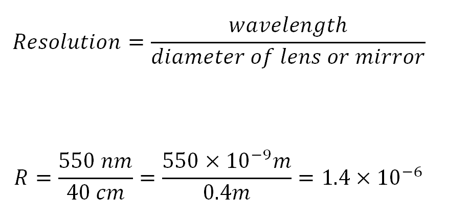
Definition of optical power
Determining its numerical value

      The method we have just described, and which has been carried out a great number of times, always results in bringing optical surfaces fairly quickly to a degree of perfection which can not be surpassed. When one arrives at that point, one needs to ask whether the impossibility of making any more progress lies in the imperfection of our procedure, or whether it lies in the fact that one has reached the goal of creating a perfect surface. For us the question is not in doubt, and we will not hesitate to consider as perfect a surface which acts as far as we can tell upon light as would a mirror that corresponds precisely to the figure required by optical theory.

.
When a surface approaches this degree of relative perfection, one can watch an ensemble of characteristics intervene which, once understood, can serve as a guide for the worker and give notice that the work can be considered finished. At the same time as the defects disappear that are revealed by the various optical testing methods, the image, as seen under a microscope, produced by such a surface takes on a particular appearance that pleases the eye and does not disappear even when uses great enlarging powers. This remarkable appearance comes from the fact that the image is being formed by a grouping of correctly circular elements. Each of these elementary disks is in fact surrounded by a certain number of rings; but since the latter have rapidly decreasing intensities, the central disk has so much more brightness that it has the preponderance of the precise outline of the contours of light. Of the various rings that surround this disk, one can normally only see the first one. And since a dark interval separates them, the result is that this first bright ring does not bring any appreciable confusion to the image. Also, since it is superimposed on itself, it merely draws a pale belt that runs around, and is parallel to, the brightest contours of the image.

.
The theory of diffraction explains this phenomenon, which implies that all the rays of the convergent light come to its vertex almost completely in phase vibrationally. If we could substitute a surface that is rigorously exact for the approximate surface obtained via our experimental methods, the rays would arrive at the vertex in perfect accord. But the point of light – or rather, the narrow disk – formed by their coming together would still be surrounded by no less rings than before. Therefore there is no practical point in trying to push surfaces beyond the degree needed for the appearance of diffraction phenomena.

.
When these phenomena become apparent at the focus, or in other words, when the image of a point formed by the entire uncovered mirror appears in the form of a disk surrounded by rings whose brightness decreases rapidly, then we can be assured that such a mirror, aimed at any sort of object, whether on earth or in the heavens, will produce good images, and will give optical results corresponding to its diameter.

.
      To judge the result with certainty, and to express those results in a form less vague than one normally uses in ordinary language, we should mount the mirror in a Newtonian telescope and aim it at a distant target. We should arrange this target is as to provide details placed at the limit of visibility. We construct these test targets by inscribing on a sheet of ivory a series of divisions arranged into successive groups, where the millimeter is divided into smaller and smaller parts. The thickness of the lines engraved should vary from one group to the next in such a way that the darkened portion has the same area as the interval that separates them (figure 18). If one views such a target placed at a distance, or if one observes it with too weak an optical instrument, then the different groups appear merely to have a uniform light gray color. But if one decreases the distance or uses more powerful optics, one sees that the groups that are the farthest apart resolve themselves into distinct lines, while the rest remain blurred.

.
When we increase the enlargement and illuminate the target sufficiently, we can conclude that in the groups that uniformly gray, the blurriness of the lines cannot be attributed to the weakness of the eye. It must be entirely because the instrument resolves one of the groups and does not resolve the next one. In verifying in this way which of the groups is so close together as to be located at the limit of visibility, we obtain positive proof that the instrument can separate the parts that are separated by a certain angle, and cannot separate those that are closer together than that. It then follows that the ability of the instrument to penetrate the details of observed objects, or what we could call its optical power, is inversely proportional to the angular limit of separability of the adjacent divisions. The definitive expression of this optical power is the quotient of the distance to the target, divided by the mean interval between the finest visible divisions.

.
To this sort of test we have submitted a great number of mirrors of all sizes and of all focal lengths. These experiments have led us to a general expression of optical powers which is remarkably simple. We have found that this optical power is independent of focal length, that it varies only with the diameter of the mirror, and that it works out to about 150,000 units per centimeter of diameter. Without having done as many experiments on achromatic objectives, we have nonetheless discovered that, when we reduce them to their active surface diameter, they obey the same law, and that if the diameters are equal, then both lens and mirror are capable of having the same optical power.

.
This fact, which appears to be henceforth well-established, naturally leads one to search in the physical make up of light, and not in the imperfections of our instruments, for the obstacle which limits the extension of the effects already obtained. No matter how the optics are constructed, these instruments, as long as they approach perfection, tend to display optical powers that are in a constant ratio with the respective diameters of the ray bundles that are transmitted. One can not refrain from considering this ratio as a physical constant whose value expresses the aptitude of light for forming detailed images. In taking a millimeter as our unit of length, to which we normally relates the wavelength of light, we find, according to our experiments on optical powers, that this this constant has a value of 1500.

.
This optical constant of light is intimately linked to the wavelength of light and is inversely proportional to it, so that it varies for light of different colors. This means that rays that are more easily refracted [i.e., shorter wave length light, such as blue light – trans.] produce the greatest power of definition. Experiments have confirmed this numerous times, especially via the clarity of microphotographs taken with ultraviolet light.

.
In general, physical constants have a reason for their existence which flows directly from the nature of the agent whose physical properties are being defined. Evidently this number 1500, which expresses in some way the separability of points of light, proceeds from the number of light waves contained in a unit of length, and multiplied by a coefficient that depends both on the procedure used to determine optical power and also on the physiological aptitude of the retina to perceive different impressions.

.
It may be feared that while trying to give rise to the notion of optical power, will unwillingly provoke optical workers to announce impossible powers. But anything is liable to be distorted. To help put other observers on guard against illusory observations, we have taken care to explain precisely the way to obtain comparable measurements. We also maintain that there is an absolute limit to how high the magnification can be raised in practice by any optical instrument.

.
Nonetheless, we need to reserve the case where our instruments will be tested on the sky.

.
When the weather is very fine, it can happen that the observation of double stars with equal magnitude reveals an optical power that is higher, even up to twice the result that one would conclude from terrestrial targets. Here is an explanation for this possible anomaly. With our terrestrial target, the details we are trying to distinguish are equal spaces, alternately black and white. That was a necessary arrangement so that we could always fall back on identical conditions of lighting and observation. But this equality of black and white is far from being the best arrangement as far as one’s ability to resolve detail is concerned. In the image of such an arrangement, the width of the white areas equals their geometric area increased by the apparent diameter inherent in the width of the elementary [Airy? — trans.] disks, so that at the moment that these white areas begin to merge, they have a width that is twice the one they would present if the white parts were infinitely small in comparison to the black parts. However, in the sky the real dimensions of double stars are infinitely small in relation tot he space between them. Thus, the width of the image of these stars is reduced to these elementary disks, which makes it so that their angular separation, with a homogeneous atmosphere, is easier than with the ivory target. We are not yet able to state how much higher the optical power determined via double stars is than that obtained by viewing the ivory target, but we are sure that the difference is considerable. A 33-cm telescope, which gave us our first opportunity to witness the fact that the blue companion star of Gamma Andromedae is a double, only had a computed optical power of 400,000, which indicated that it should theoretically only have been able to resolve one half arc-second. However, it is estimated that the angle of separation between the blue binary stars of Gamma Andromedae is 4/10 of an arc-second.

.
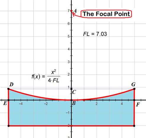
We have stated, in a general way, that in a perfect instrument the optical power is independent of the focal length. If we want to understand this fully, then we should analyze the constitution of the images of objects by following the theoretical deductions step by step. In a perfect image, the number of distinct points clearly depends on the size of the elementary disks that represent the different points of the object. Since these disks are surrounded by a dark circle which is the geometric locus of all of the points where one-half of the bundle of light rays is out of phase with the other half, it follows that the size of these disks depends both on the wave length of light and the angle of convergence of the rays at the extremities. For a fixed wave length, and for a constant diameter of the base of the bundle of rays, the width of the image varies with the focal length. But since the size of the elementary disks varies noticeably in the same ratio, the result is that the number of different parts does not change. Because of this sort of logic, we have been led to construct short-focal-length telescopes without fear of affecting their optical power.

.
But if this optical power only depends on the useful surface of the objective, then one should expect that in reducing the active surface of a good mirror by using a diaphragm or stop, one should reduce the optical effects of the mirror in proportion. This result, which was foreseen, seemed to be so contrary to what ordinarily occurs that it seemed wise to us to check it directly.

.
This experiment has been repeated several times on telescopes of all sizes, and it has now been confirmed that by local refiguring one can bring mirrors to such a degree of perfection that they cannot be subjected to any diaphragm or stop without losing some of their optical power. From this flows a new character and a very simple test that can be used to check the quality of a telescope; for depending on whether they gain or lose in optical quality as they are stopped down, we can judge in a decisive manner how nearly they approach perfection.

.
All of these facts are additional confirmations in favor of the wave theory of light. In the former theory, the focus is simply the point where independent rays cross each other; the more rays, the brighter it is, but the smaller the probability that this crossing will occur at a unique point. But according to wave theory, the focus that forms in a homogeneous medium is the center of spherical waves with the same phase; the longer the wave length, the better this center is determined. The rays we consider geometrically have no individual existence; they are simply the direction of propagation of waves. Among these supposed rays that a surface is supposed to regroup at a focus, all are special: those that vibrate in phase constitute a limited focus; those that because of a surface imperfection have undergone a difference in travel path that incapable of putting them out of phase, are pushed a certain distance away from the others without ever being able to come closer to them than a certain limit. There is a discontinuity between the waves that are in phase and those that are out of phase, and this discontinuity reveals itself by the presence of a black circle that stands like a rampart around the large center of the effective rays. However, if by refiguring one is able to bring back those deviated rays, one will find that they will never penetrate that dark space; they avoid it and cross it as the effect of an unstable equilibrium, only to reunite themselves by pressing themselves against the group of in-phase rays.

.
This discontinuity in the path of the rays that are called upon to become effective, explains a phenomenon whose singularity has often struck us. When a surface, even a very incorrect one, is merely one of revolution, the phenomenon that one notices during the various focusing maneuvers consists in the fact that, in a greater or smaller area on either side of the point of best focus, one notices the presence of an image that remains clear, while still detaching itself on a background of ambient light. Assuredly, if the deviated rays could approach the focus closer and closer, this phenomenon would not appear, given that the successive foci formed by the different zones are continuously linked one to the next. But since in reality every focus is limited and essentially preserved from the confusion by a black annulus, whatever zone forms an image in the plane being observed in, is bounded on either side by inactive zones which assure to their own images the ability to dominate over the lighted background formed by the brusque dissemination of other rays.

.
The same explanation accounts for the phenomenon of doubling which occurs so frequently with large instruments. Opticians assume that doubling of images is due to an accident in their work which divides the surface of the objective into two discontinuous regions separated by a “parting” ridge. This explanation has no foundation, because one never finds an intersection between two regions, nor any surface discontinuity. In reality, image doubling is a result of the superposition in the converging apparatus of two distinct defects. It happens every time that the objective is marred with a positive or negative general aberration and also presents two central rectangular sections with unequal curvatures. We have discovered, when discussing the paths that have been followed, that in such a case there are formed in the converting ray pencil to excentric groups of active rays, and that the central rays that remain out of phase become inactive in their perpendicular direction. We can produce, at will, the phenomenon of image doubling by choosing a mirror affected by aberration and then compressing it along one of its diameters. When the aberration is positive, the doubling occurs perpendicular to the compressed diameter; if the aberration is negative, the doubling is parallel to that same diameter.

.
If we consider now that this ring surrounding the focal image of each point of light, and which works so powerfully to give definition to images, also has the effect of rejecting the rays that would harm the useful rays at a noticeable distance, then we can judge how much its presence must favor the application of our third method of examining optical surfaces. That method is precisely designed to establish how much those rays depart from one another, by the interposition of an opaque knife-edge screen.

.
When after doing refiguring all the harmful rays have returned into order, one can still not conclude, as we have already stated, that the reflecting surface has attained geometric perfection in all its rigor. However, the result is that the remaining defects are contained within limits which one can determine by very simple calculations. The formation of an exact focus implies the rigorous concordance or the absolute equality of the paths traveled by all of the rays. If a focus forms that appears perfect, it is not exaggerating to say that all the rays are in phase to at most one-half wave length, because those that were out of phase by any more than that would be rejected outside the first black ring, and would end up reinforcing the exterior rings. Now the average wave-length of light is about half of a thousandth of a millimeter, and a half-wavelength is a quarter of a thousandth [ of a millimeter]. But if any part of the surface is in error by a certain amount, then this error will act upon the paths traveled, whereupon it will be doubled by reflection. And since we have assumed that all of the rays are in step by less than one-half wavelength, it results that all the points on the actual physical surface of the mirror approach the theoretical surface by less than one eight-thousandth of a millimeter, or roughly one ten-thousandth of a millimeter.

.
Independent of the size of the surfaces, that is the degree of perfection which comprises local refiguring pushed to the point where we realize foci that are physically perfect. If we use the spherometer to test quantities of this order, it can only respond with uncertainty; how then can any machine working the glass attain them? We must therefore work by hand. But even the human hand cannot work alone; it must constantly be guided by the hints from the light itself.

.
To sum up, in this section, devoted specially to optical power, we have established that there is a group of characters by which one can tell that a surface approaches perfection. When such surfaces are subjected to examination, they cease to show any perceptible defects. The images they give take on a good appearance that is maintained under very strong enlargement, the contours are clear and can be seen accompanied by pale diffraction fringes. Also, when one applies a diaphragm stop, one notices that no portion of the objective can be masked off without a comparable weakening of the optical effects.

.
In order to give a numerical value to the concept of optical power, we consider it to be inversely proportional to the smallest angle under which one can observe the separation of the smallest details visible in the focus of an instrument. We took as our test subject a distant target formed by contiguous, alternating black and white spaces, placed at the limit of visibility on account of its distance from the telescope and the distances between the black and white areas. We expressed the optical power as the quotient of the distance from the target to the focal point of the telescope, divided by the mean separation between homologous sections in the target.

.
After a large number of experiments performed on mirrors and lenses of all sizes and focal lengths, we have determined that the optical power depends only on the diameter of the effective surface. Consequently, this power and this diameter are in a constant ratio characteristic of white light, and which expresses in a general way the delicacy of the agent or its virtual power of separation.

.
If we take the millimeter as our unit of length, to which the wavelength of light is normally linked, we find that this optical power is a number approximately equal to 1500. From this, we can deduce by a simple proportion the maximum optical power of any objective of any size.

.
We insist that there does really exist an absolute limiting power, so as to establish that which one should be able to expect from a telescope of any given size, and also to deter manufacturers from claiming to have obtained or trying to obtain optical results that are simply impossible.

← Older posts
Newer posts →

Subscribe

  • Entries (RSS)
  • Comments (RSS)

Archives

  • December 2025
  • November 2025
  • October 2025
  • September 2025
  • July 2025
  • January 2025
  • November 2024
  • October 2024
  • August 2024
  • July 2024
  • May 2024
  • April 2024
  • January 2024
  • December 2023
  • October 2023
  • August 2023
  • June 2023
  • May 2023
  • April 2023
  • November 2022
  • October 2022
  • August 2022
  • July 2022
  • June 2022
  • May 2022
  • April 2022
  • February 2022
  • January 2022
  • December 2021
  • October 2021
  • September 2021
  • August 2021
  • July 2021
  • June 2021
  • May 2021
  • March 2021
  • December 2020
  • October 2020
  • September 2020
  • August 2020
  • March 2020
  • February 2020
  • January 2020
  • December 2019
  • November 2019
  • September 2019
  • August 2019
  • June 2019
  • May 2019
  • January 2019
  • November 2018
  • October 2018
  • September 2018
  • August 2018
  • May 2018
  • March 2018
  • January 2018
  • November 2017
  • October 2017
  • September 2017
  • August 2017
  • July 2017
  • June 2017
  • May 2017
  • April 2017
  • February 2017
  • December 2016
  • September 2016
  • June 2016
  • May 2016
  • April 2016
  • March 2016
  • February 2016
  • January 2016
  • December 2015
  • November 2015
  • August 2015
  • July 2015
  • April 2015
  • March 2015
  • February 2015
  • January 2015
  • December 2014

Categories

  • astronomy
  • astrophysics
  • education
  • flat
  • History
  • Hopewell Observatorry
  • Math
  • monochromatic
  • nature
  • optical flat
  • Optics
  • Safety
  • science
  • teaching
  • Telescope Making
  • Uncategorized

Meta

  • Create account
  • Log in

Blog at WordPress.com.

  • Subscribe Subscribed
    • Guy's Math & Astro Blog
    • Join 53 other subscribers
    • Already have a WordPress.com account? Log in now.
    • Guy's Math & Astro Blog
    • Subscribe Subscribed
    • Sign up
    • Log in
    • Report this content
    • View site in Reader
    • Manage subscriptions
    • Collapse this bar
 

Loading Comments...