Here is some information that teachers at quite a few different levels could use* for a really interesting geometry lesson involving reflections involving two or more mirrors, placed at various angles!
Certain specific angles have very special effects, including 90, 72, 60, 45 degrees … But WHY?
This could be done with actual mirrors and a protractor, or with geometry software like Geometer’s Sketchpad or Desmos. Students could also end up making their own kaleidoscopes – either with little bits of colored plastic at the end or else with some sort of a wide-angle lens. (You can find many easy directions online for doing just that; some kits are a lot more optically perfect than others, but I don’t think I’ve even seen a kaleidoscope that had its mirrors set at any angle other than 60 degrees!)
I am reproducing a couple of the images and text that Angel Gilding provides on their website (which they set up to sell silvering kits (about which I’ve posted before, and which I am going to attempt using pretty soon)).

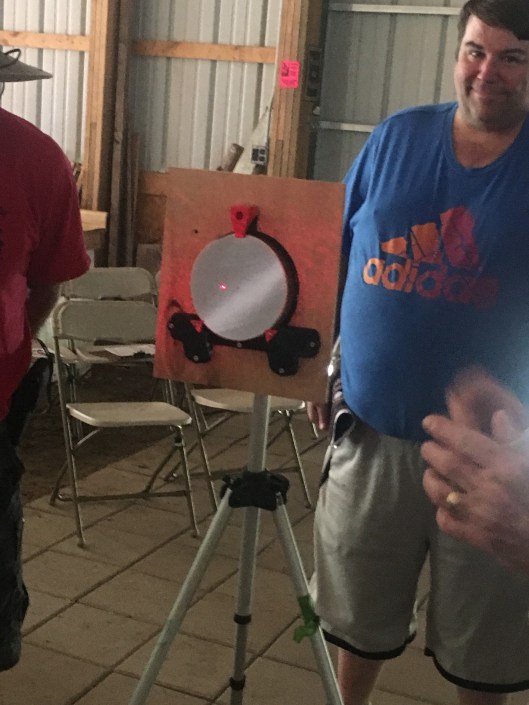
At 72º you see 4 complete reflections.

When two mirrors are parallel to each other, the number of reflections is infinite. Placing one mirror at a slight angle causes the reflections to curve.
https://angelgilding.com/multiple-reflections/
===========
Rant, in the form of a long footnote:
* assuming that the teacher are still allowed to initiate and carry out interesting projects for their students to use, and aren’t forced to follow a scripted curriculum. It would be a lot better use of computers than forcing kids to painfully walk through (and cheat, and goof off a lot) when an entire class is forced to use one of those very expensive but basically worthless highly-centralized, district-purchased computer-managed-instruction apps. God, what a waste of time – from personal experience attempting to be a volunteer community math tutor at such a school, and also from my experience as a paid or volunteer tutor in helping many many students who have had to use such programs as homework. Also when I was required to use them in my own classes, over a decade ago, I and most of my colleagues found them a waste of time. (Not all – I got officially reprimanded for telling my department chair that ‘Renaissance Math’ was either a ‘pile of crap’ or a ‘pile of shit’ to my then-department head, in the hearing of one of the APs, on a teacher-only day.
Keep in mind: I’m no Luddite! I realized early on that in math, science, and art, computers would be very, very useful. I learned how to write programs in BASIC on one of the very first time-share networks, 45 years ago. For the first ten years that my school system there was almost no decent useful software for math teachers to use with their classes unless you had AppleII computers. We had Commodore-64’s which were totally incompatible and there were very few companies (Sunburst was one) putting out any decent software for the latter. So when I saw some great ideas that would be ideal for kids to use on computers to make thinking about numbers, graphs, and equations actually fun and mentally engaging, often I would have to write them my self during whatever free time I could catch, at nights and weekends. Of course, doing this while being a daddy to 2 kids, and still trying to teach JHS math to a full load of students (100 to 150 different kids a day at Francis Junior High School) and running a school math club and later coaching soccer. (I won’t say I was a perfect person or a perfect teacher. I believe I learned to give better math explanations than most, didn’t believe that you either have a ‘m,ath gene’ or you don’t, at times had some interesting projects, and at times was very patient and clear, but had a terrible temper and often not good at defusing things. Ask my kids or my former students!) Later on, I collaborated with some French math teachers and a computer programmer to try to make an app/program called Geometrix for American geometry classes that was supposed to help kids figure out how to make all sorts of geometric constructions and then develop a proof of some property of that situation. It was a failure. I was the one writing the American version, including constructions and tasks from the text I was currently using. There was no way I could anticipate what sorts of obstacles students would find when using this program, until I had actual guinea pig students to use them with. Turns out the final crunch of writing however many hundreds of exercises took place over the summer, and no students to try them on. Figuring out hints and clues would require watching a whole bunch of kids and seeing what they were getting right or wrong. In other words, a lot of people’s full time job for a long time, maybe paying the kids as well to try it out so as to get good feedback, and so on. Maybe it could work, but it would require a lot more investment of resources that the tiny French and American companies involved could afford. We would have really needed a team of people, not just me and a single checker.
I find that none of these computer-dominated online learning programs (much less the one I worked on) can take the place of a good teacher. Being in class, listening to and communicating logically or emotionally with a number of other students and a knowledgeable adult or two, is in itself an extremely important skill to learn. It’s also the best way to absorb new material in a way that will make sense and be added to one’s store of knowledge. That sort of group interaction is simply IMPOSSIBLE in a class where everybody is completely atomized and is on their own electronic device, engaged or not.
Without a human being trying to make sense out of the material, what I found quite consistently, in all the computerized settings, that most students absorbed nothing at all or else the wrong lessons altogether (such as, ‘if you randomly try all the multiple choice answers, you’ll eventually pick the right one and you can move on to some other stupid screen’; it doesn’t matter that all your prior choices were wrong; sometimes you get lucky and pick the right one first or second! Whee! It’s like a slot machine at a casino!).
By contrast, I found that with programs/apps/languages like Logo, Darts, Green Globs, or Geometer’s Sketchpad, with teacher guidance, students actually got engaged in the process, had fun, and learned something.
I find the canned computer “explanations” are almost always ignored by the students, and are sometimes flat-out wrong. Other times, although they may be mathematically correct, they assume either way too much or way too little, or else are just plain confusing. I have yet to detect much of any learning going on because of those programs.


/some-california-residents-opting-to-shutter-their-pools-due-to-state-s-severe-drought-468923226-57c109745f9b5855e5ad8da7.jpg)


")
")
")
")
")
")