• My series on making a Newtonian telescope
  • How Leon Foucault Made Telescopes

Guy's Math & Astro Blog

Guy's Math & Astro Blog

Tag Archives: alt-az

An amazing little telescope

06 Tuesday Aug 2024

Posted by gfbrandenburg in astronomy, astrophysics, Optics, science

≈ Leave a comment

Tags

alt-az, astronomy, electronics, focus, Hopewell Observatory, light pollution, optical tube assembly, Optics, refractor, solar system, Telescope, Washington

Look what this little thing can do that I’ve always failed at myself, even with an entire observatory at my disposal: take decent astrophotos.

Here it is on a home made tripod, taking photos of the sun. Notice the reflective solar filter. Here are two images:

The device woke up, and after less than a minute of self’s-calibration, it pointed very accurately at the sun and focused itself perfectly. It produces a continuous feed; I even did 100 frames of a time-lapse. It’s all stored on my cell phone but I can share the photos or even live views with folks nearby.

And from night time spots here in DC and NOVA:

This can take tolerable astrophotos even when surrounded by streetlights!

.

One Way to Build an Alt-Az Newtonian Telescope

16 Tuesday Dec 2014

Posted by gfbrandenburg in Telescope Making

≈ 2 Comments

Tags

alt-az, dobsonian

One Way to Build a 6-inch Dobsonian-Newtonian Alt-Az Sonotube Telescope


Instructions written by Guy Brandenburg

February 2007

Acknowledgements and thanks to Mel Bartels, Richard Berry, Bill Blackmore, Jack Booth, John Dobson, David Kriege, Jerry Schnall, Jean Texereau, and many others whom I can’t remember at the moment. I have modified their ideas somewhat, hopefully for the better. However, the typos and errors are all mine.
  1. Cradle and altitude trunnions
    1. The purpose of the cradle is to hold the tube steady but also allow for changing the altitude angle and changing the balance point when additional items are added to the telescope, and to allow the user to put the focuser at a convenient angle by rotating the tube.
    2. The cradle consists of four rectangular pieces of plywood that are glued and screwed to form a box that the tube fits in, and two altitude trunnions that each consist of a plywood disk and a ring cut from a PVC sewer pipe. The pipe fits onto the plywood disk and is held there by friction. See diagram below.                           make a dob pic 1
    3. Use 2-inch deck screws, and glue, to attach the 9+3/4” by 12” pieces of plywood to the 8+1/4” by 12” pieces of plywood. Three or four screws per edge should be enough. Use plenty of glue, and use a damp paper towel to wipe up the glue that oozes out. It is not necessary to counter-sink the screws. Make sure everything is lined up properly before inserting the first screw. If you want, you can nail in a couple of small nails (say, 2” long) to hold things in place before you put in any screws.
    4. Before attaching the plywood disks that hold the PVC plastic trunnions, it is advisable to draw the diagonals as shown. This will help you make sure that the disk is centered correctly.
    5. When the glue is somewhat dry, this all can be painted, inside and out.
    6. When the paint is dry, then you can attach the handle and fit the PVC trunnions onto the plywood disks. It is supposed to go on with difficulty, so that it won’t come off easily. It should not need to be nailed, glued, or screwed.
  2. Optical Tube
    1. The tube
      1. The tube itself is made of thick cardboard designed for casting cylindrical concrete columns. One brand name for these is Sonotube. When painted, it is strong, relatively rigid and light, and reasonably waterproof, and it’s quite inexpensive: $5 for a 4-foot length of tube. (Carbon fiber composite tubes, which are lighter, stronger, more rigid and much more waterproof, would cost nearly 100 times as much.) The purpose of the tube is to hold the optical components rigidly, in the proper alignment so that the user can look at things.
      2. A 1+1/2” diameter hole will need to be drilled near the front end of the tube for the focuser. Use an ordinary hole saw attached to an electric drill for this. If you are using a 3- or 4-vane spider, measure and drill the holes for this now.            make a dob pic 2
  • It is very important to paint the inside of the tube using flat black paint. I strongly recommend using latex paint so that any drips can be washed off with water, likewise the brush, and so that the fumes are not so bad. Two or more coats are desirable. However, the tube is quite long, and you don’t want to get paint all over your arm. How to reach the middle? One way is to tape your brush to the end of a dowel rod (or other scrap piece of wood) with duct tape, and use that to extend your reach. When you have finished painting the inside, leave the tube to dry in a horizontal position so that air can circulate; or else, if you want to let it dry in a vertical position, make sure that you put it on some little scrap pieces of wood so that air can circulate up and down the tube. Be sure to wash the brush as soon as you are finished painting. Use lots of water and even some hand soap and rinse it very thoroughly.
  1. The outside of the tube also needs to be painted. Any color will do – the wilder the better, in my opinion. See the previous remarks about latex paint. It is a good idea to let the tube dry in a vertical position, propped up on little scraps of wood. Be sure to paint the edges where holes have been cut and the ends of the tube; when the loose cardboard is impregnated with paint, it becomes much harder.
  1. Primary Mirror Holder
    1. The purpose of this item is to hold the mirror rigidly in the correct alignment, at the proper distance from the secondary mirror and the focuser, so that whoever is looking through the telescope can actually see correctly-focused and clear images of whatever it is they are trying to observe. It is not necessary to paint this part, but it won’t hurt, either. However, the parts where the silicone caulk will hold the mirror to the wood must NOT be painted, because the caulk does not stick well at all to painted surfaces.
    2. The mount consists of two plywood disks separated by springs and held together by machine screws, washers, and wingnuts. The upper plywood disk has an outer diameter about one-half inch less than the inner diameter of the tube; so that’s about 7+1/2”. The lower plywood disk has an outer diameter that is about the same as the inner diameter of the tube, so that’s just shy of 8”. Each disk should have a good-size hole drilled in the center for ventilation. The size of the hole is not critical – any size that you have a hole saw for will work fine.
  • The two disks also need to have 3 holes drilled in them at 120 degrees from each other so that the machine screws can go through. The hole in the upper disk should be countersunk so that the machine screw head will not protrude. The hole in the lower disk should be considerably larger than the screw itself, so that the entire assembly can be adjusted easily. Be sure to line the two disks up together before drilling the holes, and mark how they are supposed to go.
  1. A small piece of steel (or any other convenient metal) should be fabricated into an L shape, with a hole in both parts. The hole in the horizontal part will hold a single, small screw to attach the L to the upper plywood disk, and the hole in the vertical part will be used to squirt the silicone glue through, to hold the mirror in place.
  2. When the entire setup is assembled, except for the glueing of the mirror, then lay three ordinary nails underneath where the mirror will go, as temporary spacers. Squirt nice thick blobs of glue in the three locations previously chosen, then carefully place the mirror in the correct location. Then squirt three more globs of glue, one at each of the three L-shaped edge holders. Then put the entire assembly away somewhere level, safe, and dry, with ventilation and protection from dust, so that it will not be disturbed for a couple of days while the glue sets.
  3. See the diagrams for construction details, and below that for an example by a local ATMer, JCN.                                                                    make a dob pic 3Make a dob pic 4
  • The primary mirror cell is about the last thing to be placed in the telescope. It goes in AFTER the focuser and secondary are put in place, and after everything is assembled, painted, and dried. In my experience, it is not possible to calculate exactly where the mirror should go in the telescope; none of the formulas I’ve seen work exactly. The best one can do is to estimate it, but then the exact location will depend on your eyepieces, the height of your focuser, and your eyes. So, once the rest of the scope is together, you carefully slide the primary mirror cell – with its mirror in place – up into the tube to where you think it should go, and do a very rough alignment of the mirror by looking down the tube. Use shims to get it to stay in place temporarily, and try to focus on as distant an object as possible by daylight. To get it to come into focus will probably require pushing or pulling the entire cell forward or back. Then try the entire process at night, when you can see the moon or a very bright star such as Vega or Sirius. It will not focus the same way, I guarantee! When you have the mirror in such a location that stellar objects come into focus, THEN you can use deck or drywall screws to screw it permanently into place in the tube.

make a dob pic 5cell holder variant by JCN

  1. Focuser
    1. The purpose of the focuser is to hold an eyepiece at the very end of the voyage of all of those photons from outer space so that your eye can detect an image.
    2. Unless you are doing astrophotography, a simple rack-and-pinion focuser with a knob will do just fine. The standard size focuser and eyepiece for decent, smaller telescopes (under 12” diameter) is 1/25”. Plastic-and-metal ones work fine unless seriously abused. There are ones designed for refractors, and ones designed for reflectors. Get the latter type, unless you are building a refractor!
  • Use small nuts and bolts to attach them to the telescope tube.
  1. Unfortunately, some focusers will require a shim to be fabricated underneath so that there will not be a light gap between the focuser and the telescope tube. This all depends on the focuser and the tube you are getting.
  2. As mentioned earlier, you will need to cut a hole in your tube large enough to fit your focuser.
  1. End Ring
    1. The purpose of this is to strengthen the end of the telescope tube that points towards the sky.
    2. Use a decent-quality plywood and a router to cut a ring with a thickness of roughly an inch that will fit tightly onto the end of the tube. Our tubes are 8+1/4” OD, so that should be the ID of the ring. After routing it, sand it to remove burrs and splinters, fit it onto the tube, apply some glue and small nails, and let it dry.
  • Only make an upper end ring; not a bottom end ring, or else you won’t be able to view objects near the zenith.
  1. Mid Ring
    1. The purpose of this is to allow the telescope to stay in place at the chosen balance position, and to allow the user to rotate the tube and to adjust the balance if needed.
    2. The instructions for cutting this are very much like the end ring. The difference is that there should be a small amount of ‘play’ or room for the ring to move over the tube, so that with some force and perhaps a mallet it can be moved when desired. Thus its interior diameter should perhaps be 8+5/16” when cut. Paint will reduce that slightly.
  • The mid ring is NOT glued or nailed to the tube. It should be able to slide, with difficulty.


  1. Secondary Diagonal Mirror, holder, and spider
    1. The purpose of the secondary diagonal mirror is to re-direct the light from the object of interest out the side of the telescope, so that you can see the object without your head getting in the way.
    2. You can build this or make all of these parts. Unless you are very good with your hands and with making small metal parts, I suggest you buy them. The mirror itself is a true optical flat, and is easier to make on a machine than by hand.
  • Before putting this in place, it is necessary to find the exact center of the secondary mirror, and to measure the distance from this to the level of the screws that hold the spider in place against the wall of the tube. Measure and re-measure, then drill the appropriate holes, and fasten it all in place. (Remove the mirror itself while installing the spider vanes, so that dust and fingerprints don’t get on the surface of the mirror.)
  1. Finder Scope
    1. The purpose of the finder scope is to allow the user of the telescope to aim it at an object of interest. It gives the user a wider field of view than the telescope itself, which can have a field of view as small as hundredths of a degree.
    2. I strongly suggest a Telrad or other similar 1-power non-magnifying heads-up finder. These devices allow you to aim your telescope intuitively at familiar objects and then to star-hop to other objects. Then, as your budget permits, you can upgrade to other finders – and there is a wide variety to choose from!


  1. Rocker Box
    1. The purpose of the rocker box is to hold the telescope rigidly upright and to provide a place for the altitude trunnions to fit into, so that the telescope can be aimed up and down, and left and right, just like a cannon.
    2. The rocker box is made out of 4 pieces of ¾-inch plywood. It has a front, two sides, and a bottom, but no back and no top. The front is shorter than the sides, so that the telescope can be aimed at the horizon if desired. The pieces will be glued and screwed together. The two sides will have nearly semi-circular holes cut out of the tops to hold the trunnions bearings.
    3. Need to cut out the following:
  1. Bottom: one piece 11+1/4” by 10+1/2” plywood. A one-half inch diameter hole should be drilled at its exact center.
  2. Sides: Two pieces that are 11+1/4” by 33” plywood (can be a little longer if desired). Make it so that they are left-right symmetrical, so that the good side of the plywood will be facing out. Cut an arc at the top of each side to fit the trunnions.
  • Front: One piece 11+1/4” by 25” (this height can be changed, but should be about 8 inches less than the sides)
    1. Five or six deck screws, 2” long, on each vertical edge, should be enough. Be sure to use glue as well. The bottom edges could use about 3 screws per edge. Clamp the edges for about 30 minutes after glueing, and remove excess glue with a damp rag. Except for the underneath portion, this can be painted. After drying, this will be attached to the base plate.
    2. Two pieces of Teflon will make sliding contact with the PVC trunnions. They will be glued or nailed into place at the tops of the cut-out arcs at the tops of the side pieces.

make a dob pic 6

make a dob pic 7

  1. Base Plate, or Azimuth Disk
    1. The purpose of the base plate is to allow the rocker box to swivel left and right, so that the user can aim the telescope at anything he or she wants to look at, in any part of the sky.
    2. This base plate is the invention of John Dobson, a master scrounger, all-round eccentric amateur astronomer, and former monk who lives in California. It consists of a downward-facing surface of Formica, Wilsonart, or some similar type of counter-top laminate, resting on three Teflon pads attached to an upward-facing surface. Unlike telescopes made from metal parts, this mounting rotates very smoothly and does not have any backlash at all. That is, if you move the telescope to a given position and let it go, it will stay where you leave it.
    3. To cut out:
  1. two 15-inch diameter circular disks from the same ¾” plywood. The precise size is not critical. Using the jig that we have in our shop, you need to drill a ½-inch hole at the exact center of the disks first, and then cut them out, only cutting through half of the plywood at a time, flipping them over for the second cut.
  2. One piece of countertop laminate – any type will do – a square 16” by 16” is fine.
    1. Choose which will be the upper disk, and which part of that disk will be facing up. Use paintbrush to coat the other side of the wooden disk with a smooth layer of latex-based contact cement. Also paint the back side of the countertop laminate. Let the two surfaces dry until no longer gooey to the touch. Then place the laminate on top of the wood and press hard all over (there are special rollers for this, or you can use heavy glass bottles or heavy metal cylinders) so that they make good contact.
    2. Use a trimming router to trim off the excess laminate.
    3. Then use relatively short screws to attach the top disk to the bottom of the rocker box. Make sure the hole in the bottom of the rocker box lines up with the hole in the center of the top disk. Feel free to finish drilling the center hole through the laminate.
    4. The bottom disk will receive three pieces of Teflon pad around the edges at 120-degree intervals.
  1. Legs
    1. The purpose of the legs is to give the entire telescope a bit more stability and to raise the base of the telescope up off the ground by a few inches.
    2. I suggest using a 2×3 or 2×4 and cutting three pieces about 9 to 10 inches long, then cutting them into an L-shape or a shape a bit like a hockey stick, as shown here:    make a dob pic 8
    3. File or sand the legs so that folks won’t get splinters. Make sure there is clearance for the central pivot bolt, the aluminum plate, the nuts, and the lockwasher. Position the 3 legs 120 degrees apart, then screw and glue them into place. Some of the screws will need to be rather long.
    4. Attach the Teflon pads right over the legs themselves, as close to the edge of the disks.
  1. Now paint everything and let it all dry.
  2. Align your optics.
  3. Then go observe!

(<== Link back to the beginning of this series of articles)

Build Your Telescope Tube and Mount

16 Tuesday Dec 2014

Posted by gfbrandenburg in History, Telescope Making

≈ Leave a comment

Tags

alt-az, company 7, equatorial, hands-on-optics, plywood, teflon

7. Build the scope

A. There are many, many books and articles and websites devoted to the many, many ways of building your telescope tube and mount. We have quite a few of these books in our library, and you should definitely study them! In addition, public star parties put on by NOVAC, NCA and other local clubs often have home-made telescopes on the field, and you can ask the makers of those scopes how they did it. Fortunately for us, John Dobson came up with an excellent way of making inexpensive, easy-to-build and easy-to-use telescopes of the Newtonian model, even if he was a nut-case. Willmann-Bell publishes quite a few such books.

B. I strongly recommend an alt-az telescope mount for visual use, rather than an equatorial mount on a pier made of plumbing parts, as people used to make in the 1940s through the 1990s. (As noted earlier, if you want to do astrophotography, you will need a much more complicated and much more expensive mount that tracks the stars precisely. Building such a mount yourself is exceedingly difficult and requires precision machining and electronics!) Most important: plan to make a telescope that is easy to use and not too complicated to build! Using slight modifications of existing plans is much easier than trying something completely novel in design. If you strive for originality, you can be sure that you will need to modify and re-build parts of your invention, perhaps several times, because of problems that you didn’t consider or notice originally. (Think about what a nightmare it would be to drive a Model-T Ford automobile, the first real mass-production car, with all of its nutty and dangerous defects, compared to the comfortable and safe and reliable car that people drive today!)

C. I have a set of plans for a simple 6” Dob on this very blog. (Click for link)

D. At the CCCC, we also have a fairly decent set of hand and power tools for working with wood and metal, so you can make the rest of the telescope here if you like. Be careful, and follow safety directions!

E. We even have a wonderful assortment of ‘oops’ paints from hardware and paint stores, if you don’t mind the ghastly colors.

F. You will need at least half of a sheet of 4’ by 8’ plywood for the scope. The plywood can be any type you like, but don’t get a sheet that is warped or wet or too thin. Nice plywood like Appleply or Baltic Birch can be expensive, but it is strong and looks quite beautiful when varnished. Three-quarter inch thickness is standard, but it’s generally sold as a weird number like 23/32”.

G. You will also need the following commercially available items, some of which we usually have on hand, marked by “UOH”.

  1. Diagonal secondary flat elliptical mirror (we have a few)
  2. Secondary mirror holder
  3. Spider
  4. Focuser
  5. Eyepieces
  6. Finder scope(s) (I recommend a 1-power finder like a Telrad or a Red Dot finder, as well as another finder scope that magnifies about 5 to 10 times)
  7. Possibly a Barlow
  8. A few pieces of Teflon UOH
  9. A few square feet of Formica or the equivalent UOH
  10. Miscellaneous screws, nuts, bolts, screws, glue UOH
  11. Guidance UOH
  12. Paint UOH
  13. Random wood scraps, including a short 2-by-4 UOH
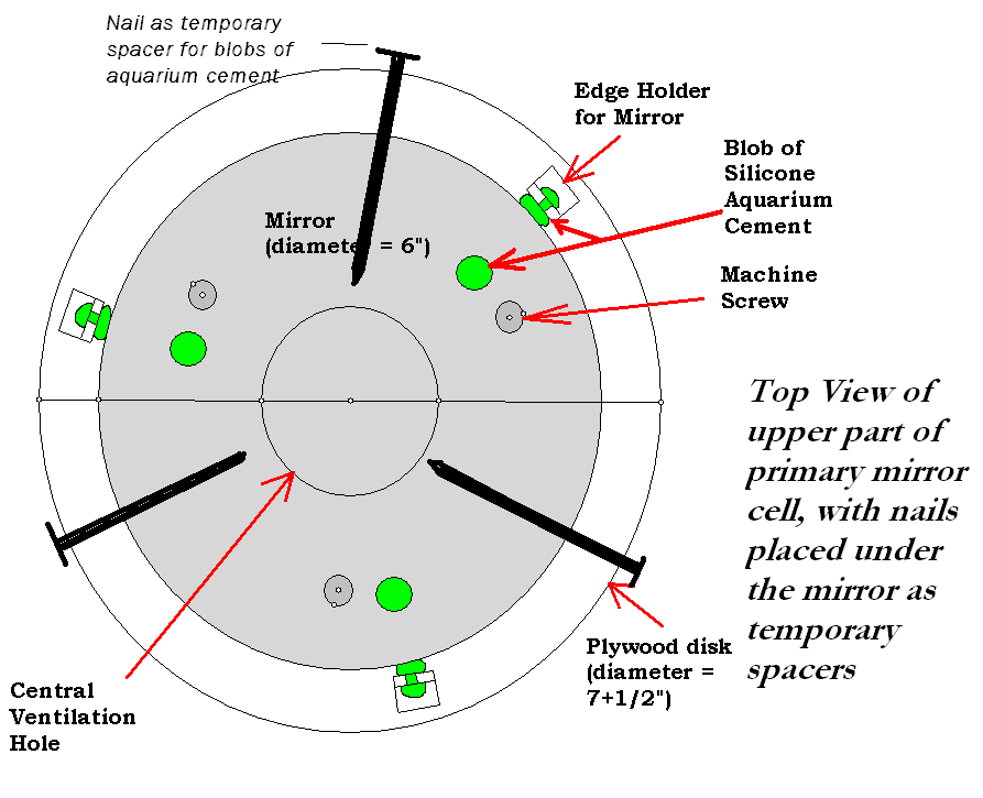
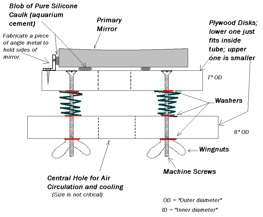
  14. For the mirror holder, you need: Three compression springs; 3 flat-headed machine screws; 9 washers; 3 wingnuts; and a small fresh tube of pure-silicone caulk or aquarium cement

H. We are very fortunate to have a local specialty store that sells telescopes and accessories to the public, called Company 7 . It’s located near Laurel, MD and has an amazing display of rare telescopes. Please shop there! (In other words, don’t talk their ears off getting their advice, and then order an item online because it’s a few dollars cheaper!)

(Link forward to the next section ==>)

(<==Link back to the previous section)

Subscribe

  • Entries (RSS)
  • Comments (RSS)

Archives

  • December 2025
  • November 2025
  • October 2025
  • September 2025
  • July 2025
  • January 2025
  • November 2024
  • October 2024
  • August 2024
  • July 2024
  • May 2024
  • April 2024
  • January 2024
  • December 2023
  • October 2023
  • August 2023
  • June 2023
  • May 2023
  • April 2023
  • November 2022
  • October 2022
  • August 2022
  • July 2022
  • June 2022
  • May 2022
  • April 2022
  • February 2022
  • January 2022
  • December 2021
  • October 2021
  • September 2021
  • August 2021
  • July 2021
  • June 2021
  • May 2021
  • March 2021
  • December 2020
  • October 2020
  • September 2020
  • August 2020
  • March 2020
  • February 2020
  • January 2020
  • December 2019
  • November 2019
  • September 2019
  • August 2019
  • June 2019
  • May 2019
  • January 2019
  • November 2018
  • October 2018
  • September 2018
  • August 2018
  • May 2018
  • March 2018
  • January 2018
  • November 2017
  • October 2017
  • September 2017
  • August 2017
  • July 2017
  • June 2017
  • May 2017
  • April 2017
  • February 2017
  • December 2016
  • September 2016
  • June 2016
  • May 2016
  • April 2016
  • March 2016
  • February 2016
  • January 2016
  • December 2015
  • November 2015
  • August 2015
  • July 2015
  • April 2015
  • March 2015
  • February 2015
  • January 2015
  • December 2014

Categories

  • astronomy
  • astrophysics
  • education
  • flat
  • History
  • Hopewell Observatorry
  • Math
  • monochromatic
  • nature
  • optical flat
  • Optics
  • Safety
  • science
  • teaching
  • Telescope Making
  • Uncategorized

Meta

  • Create account
  • Log in

Blog at WordPress.com.

  • Subscribe Subscribed
    • Guy's Math & Astro Blog
    • Join 53 other subscribers
    • Already have a WordPress.com account? Log in now.
    • Guy's Math & Astro Blog
    • Subscribe Subscribed
    • Sign up
    • Log in
    • Report this content
    • View site in Reader
    • Manage subscriptions
    • Collapse this bar
 

Loading Comments...