Tags
Algebra, dobsonian, foucault, geometry, Leon Foucault, Optics, parabola, paraboloid, Telescope, testing
Several people have helped me with this applied geometry problem, but the person who actually took the time to check my steps and point out my error was an amazing 7th grade math student I know.
It involves optical testing for the making of telescope mirrors, which is something I find fascinating, as you may have guessed. Towards the end of this very long post, you can see the corrections, if you like.
Optics themselves are amazingly mysterious. Is light a wave, or a particle, or both? Why can nothing go faster than light? We forget that humans have only very recently discovered and made use of the vast majority of the electromagnetic spectrum that is invisible to our eyes.
But enough on that. At the telescope-making workshop here in DC, I want folks to be able to make the best ordinary, parabolized, and coated mirrors possible with the least amount of hassle possible and at the lowest possible cost. Purchasing high-precision, very expensive commercial interferometers to measure the surface of the mirror is out of the question, but it turns out that very inexpensive methods have been developed for doing that – at least on Newtonian telescopes.
Tom Crone, a friend of mine who is also a fellow amateur astronomer and telescope maker, wondered how on earth we can report mirror profiles as being within a few tens of nanometers of a perfect paraboloid with such simple devices as a classic Foucault knife-edge test.
He told me his computations suggested to him that the best we could do is get it to within a few tenths of a millimeter at best, which is four orders of magnitude less precise!
I assured him that there was something in the Foucault test which produced this ten-thousand-fold increase in accuracy, but allowed that I had never tried to do the complete calculation myself. I do not recall the exact words of our several short conversations on this, but I felt that I needed to accept this as a challenge.
When I did the calculations which follow, I found, to my surprise, that one of the formulas I had been taught and had read about in many telescope-making manuals, was actually not exact, and that the one I had been told was inherently less accurate, was, in fact, perfectly correct! Alan Tarica sent me an article from 1902 supposedly explaining the derivation of a nice Foucault formula, but the author skipped a few bunch of important steps, and I don’t get anything like his results. it took me a lot of work, and help from this rising 8th grader, to find and fix my algebra errors. I now agree with the results of the author , T.H.Hussey.
I am embarrassed glad to say that even after several weeks of pretty hard work, an exact, correct formula for one of the commonly used methods for measuring ‘longitudinal aberration’ still eludes me. was pointed out to me by a student who took the time to Let’s see if anybody can follow my work and helped me out on the second method.
But first, a little background information.
Isaac Newton and Leon Foucault were right: a parabolic mirror is the easiest and cheapest way to make a high-quality telescope.
If you build or buy a Newtonian scope, especially on an easy-to-build Dobsonian mount, you will get the most high-quality photons for the money and effort spent, if you compare this type with any other type of optics at the same diameter. (Optical designs like 8-inch triplet apochromats or Ritchey-Chrétiens, or Maksutovs, or modern Schmidt-Cassegrains can cost many thousands of dollars, versus a few hundred at most for a decent 8″ diameter Newtonian).
With a Newtonian, you don’t need special types of optical glass whose indices of refraction and dispersion, and even chemical composition, must be known to many decimal places. The glass can even have bubbles and striations, or not even be transparent at all! Any telescope that only has mirrors, like a Newtonian, will have no chromatic aberration (ie, you don’t see rainbows around bright stars) because there is no refraction – except for inside your eyepieces and in your eyeball. All wavelengths of light reflect exactly the same –but they bend (refract) through glass or other materials at different angles depending on the wavelength.
Another advantage for Newtonians: you don’t need to grind and polish the radii of curvature of your two or three pieces of exotic glass to exceedingly strict tolerances. As long as you end up with a nice parabolic figure, it really doesn’t matter if your focal length ends up being a few centimeters or inches longer or shorter than you had originally planned. Also: there is only one curved mirror surface and one flat one, so you don’t need to make certain that the four or more optical axes of your mirrors and/or lenses are all perfectly parallel and perfectly concentric. Good collimation of the primary and secondary mirrors to the eyepiece helps with any scope, but it’s not nearly as critical in a Newtonian, and getting them to line up if they get knocked out of whack is also much easier to perform.
With a Newtonian, you only need to get one surface correct. That surface needs to be a paraboloid, not a section of a sphere. (Some telescopes require elliptical surfaces, or hyperbolic or spherical ones, or even more exotic geometries. A perfect sphere is the easiest surface to make, by the way.)
In the 1850’s, Leon Foucault showed how to ‘figure’ a curved piece of glass into a sufficiently perfect paraboloid and then to cover it with a thin, removable layer of extremely reflective silver. The methods that telescope makers use today to make sure that the surface is indeed a paraboloid are variations and improvements on Foucault’s methods, which you can read for yourself in my translation.
It turns out that the parabolic shape does need to be very, very accurate. In fact, over the entire surface of the mirror, other than scratches and particles of dust, there should be no areas that differ from each other and from the prescribed geometric shape by more than about one-tenth of a wavelength of green light (which I will call lambda for short), because otherwise, instead of a sharp image, you just receive a blur, because the high points on the sine waves of the light coming to you would tend to get canceled out by the low points.
Huh?
Let me try to explain. In my illustrations below, I draw two sine waves (one red, one green) that have the same exact frequency and wavelength (namely, two times pi) and the same amplitude, namely 3. They are almost perfectly in phase. Their sum is the dark blue wave. In diagram A, notice that the dark blue wave has an amplitude of six – twice as much as either the red or green sine wave. This means the blue and green waves added constructively.

Next, in diagram B, I draw the red and green waves being out of phase by one-tenth of a wave (0.10 lambda) , and then in diagram C they are ‘off’ by ¼ of a wave (0.25 lambda). You will notice that in the diagrams B and C, the dark blue wave (the sum of the other two) isn’t as tall as it was in diagram A, but it’s still taller than either the red or green one.
One-quarter wave ‘off’ is considered the maximum amount of offset allowed. Here is what happens if the amount of offset gets larger than 1/4:

In diagram D, the red and green curves differ by 1/3 of a wave (~0.33 lambda), and you notice that the blue wave (which is the sum of the other two) is exactly as tall as the red and green waves, which is not good.
Diagram E shows what happens is what happens when the waves are 2/5 (0.40 lambda) out of phase – the blue curve, the sum of the other two, now has a smaller amplitude than its components!
And finally, if the two curves differ by ½ of a wave (0.5 lambda) as in diagram F, then the green and red sine curves cancel out completely – the dark blue curve has become the x-axis, which means that you would only see a blur instead of a star or a planet. This is known as destructive interference, and it’s not what you want in your telescope!
But how on earth do we achieve such accuracy — one-tenth of the wavelength of visible light (λ/10) over an entire surface? And if we do, what does it mean, physically? And why one-tenth λ on the surface of the mirror, when ¼ λ looked pretty decent? For that last question, the reason is that when light bounces off a mirror, any deviations are multiplied by 2.
So lambda – about 55 nanometers or 5.5×10^(-8) m- is the maximum allowable depth or height of a bump or a hollow across the entire width of the mirror.
That’s really small!
How small?
Really insanely small.
Let’s try to visualize this by enlarging the mirror. At our mirror shop, we generally help folks work on mirrors whose diameters are anywhere from 11 cm (4 ¼ inches) to 45 cm (18 inches) across. Suppose we could magically enlarge an 8” (20 cm) mirror and blow it up so that it has the same diameter as the original 10-mile (16 km) square surveyed in 1790 by the Ellicott brothers and Benjamin Banneker for the 1790 Federal City. (If you didn’t know, the part on the eastern bank of the Potomac became the District of Columbia, and the part on the western bank was given back to Virginia back in 1847. That explains why Washington DC is no longer shaped like a nice rhombus/diamond/square.)
So imagine a whole lot of earth-moving equipment making a large parabolic dish where DC used to be, a bit like the Arecibo radio telescope, but about 50 times the diameter, and with a parabolic shape, unlike the spherical one that Arecibo was built with.
(Technical detail: since Arecibo was so big, there was no way to physically steer it around at desired targets in the sky. Since they couldn’t steer it, then a parabolic mirror would be useless except for directly overhead. However, a spherical mirror does NOT have a single focal point. So the scope has a movable antenna (or ‘horn’) which can move around to a variety of more-or-less focal points, which enabled them to aim the whole device a bit off to the side, so they can ‘track’ an object for about 40 minutes, which means that it can aim at targets around 5 degrees in any direction from directly overhead, but the resolution was probably not as good as it would have been if it had a fully steerable, parabolic dish. See the following diagrams comparing focal locations for spherical mirrors vs parabolic mirrors. Note that the spherical mirror has a wide range of focal locations, but the parabolic mirror has exactly one focal point.)

I’ll use the metric system because the math is easier. In enlarging a 20 cm (or 0.20 m) mirror all the way to 16 km (which is 16 000 m), one is multiplying 80,000. So if we take the 5.5×10⁻⁸ m accuracy and multiply it by eighty thousand you get 44 x 10-4 m, which means 4.4 millimeters. So, if our imaginary, ginormous 16-kilometer-wide dish was as accurate, to scale, as any ordinary home-made or commercial Newtonian mirror, then none of the bumps or valleys would be more than 4.4 millimeters too deep or too high. For comparison, an ordinary pencil is about 6.8 millimeters thick.
Wow!
So that’s the claim, but now let’s verify this mathematically.
I claim that such a 3-dimensional paraboloid, like the radio dish in the picture below, can be represented by the equation
where f represents the focal length. (For simplicity, I have put the vertex of the paraboloid at the origin, which I have called A. I have decided to make the x-axis (green, pointing to our right) be the optical and geometric axis of the mirror. The positive z-axis (also green) is pointed towards our lower left, and the y-axis (again, green) is the vertical one. The focal point is somewhere on the x-axis, near the detector; let’s pretend it’s at the red dot that I labeled as Focus.)
You may be wondering where that immediately previous formula came from. Here is an explanation:
Let us define a paraboloid as the set (or locus) of all points in 3-D space that are equidistant from a given plane and a given focal point, whose coordinates I will arbitrarily call (f, 0, 0). (When deciding on a mirror or radio dish or reflector on a searchlight, you can make the focal length anything you want.)
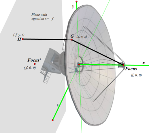
To make it simple, the plane in question will be on the opposite side of the origin; its equation is x = -f. We will pick some random point G anywhere on the surface of the parabolic dish antenna and call its coordinates (x, y, z). We will see what equation these conditions create. We then drop a perpendicular from G towards the plane with equation x = -f. Where this perpendicular hits the plane, we will call point H, whose coordinates are (-f, y, z). We need for distance GH (from the point to the plane) to equal distance from G to the Focus. Distance GH is easy: it’s just f + x. To find distance between G and Focus, I will use the 3-D distance formula:
Which, after substituting, becomes
To get rid of the radical sign, I will equate those two quantities, because FG = GH, omit the zeroes, and square both sides. I then get
Multiplying out both sides, we get
Canceling equal stuff on both sides, I get
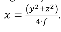
Adding 2fx to both sides, and dividing both sides by 4f, I then get
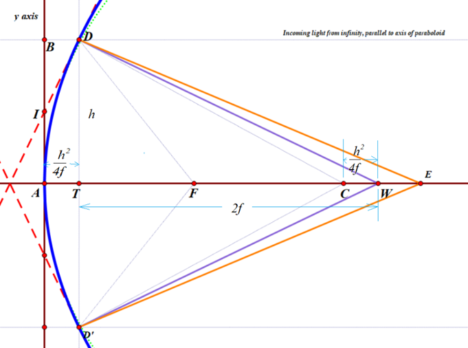
However, 3 dimensions is harder than 2 dimensions, and two dimensions will work just fine for right now. Let us just consider a slice through this paraboloid via the x-y plane, as you see below: a 2-dimensional cross-section of the 3-dimensional paraboloid, sliced through the vertex of the paraboloid, which you recall is at the origin. We can ignore the z values, because they will all be zero, so the equation for the blue parabola is
or, if you solve it for y, you get

There is a circle with almost the same curvature as the paraboloid; its center, labeled CoC (for ‘Center of Curvature’) is exactly twice as far from the origin as the focal point. You can just barely see a green dotted curve representing that circle, towards the top of the diagram, just to the right of the blue paraboloid. center of the circle (and sphere). Its radius is 2f, which obviously depends on the location of the Focus.
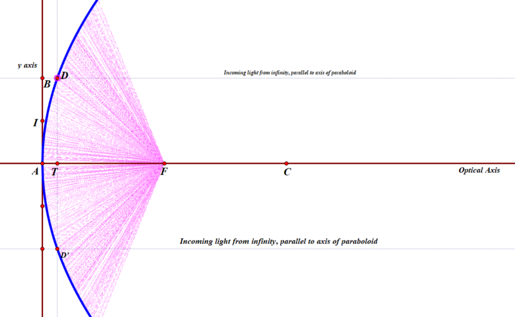
D is a random point on that parabola, much like point G was earlier, and D’ being precisely on the opposite side of the optical axis. The great thing about parabolic mirrors is that every single incoming light ray coming into the paraboloid that is parallel to the axis will reflect towards the Focus, as we saw earlier. Or else, if you want to make a lamp or searchlight, and you place a light source at the focus, then all of the light that comes from it that bounces off of the mirror will be reflected out in a parallel beam that does not spread out.
In my diagram, you can see a very thin line, parallel to the x-axis, coming in from a distant star (meaning, effectively at infinity), bouncing off the parabola, and then hitting the Focus.
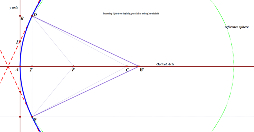
I also drew two red, dashed lines that are tangent to the paraboloid at point D and D’. I am calling the y-coordinate of point D as h (D has y-coordinate -h)and the x-coordinate of either one is
I used basic calculus to work out the slope of the red, dashed tangent line ID. (Quick reminder, if you forgot: in the very first part of most calculus classes, students learn that the derivative, or slope, of any function such as this:
is given by this:
So for the parabola with equation
the slope can be found for any value of x by plugging that value into the equation
Since
the exponent b is one-half. Therefore, the slope is going to be
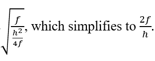
which simplifies to
Now we need to plug in the x coordinate of point D, namely
we then get that the slope is
To find the equation of the tangent line, I used the point-slope formula y – y1=m(x – x1). ; plugging in my known values, I got the result
To find where this hits the y-axis, I substituted 0 for x, and got the result that the tangent line hits the y-axis at the point (0, h/2) — which I labeled as I — or one-half of the distance from the vertex (or origin) to the ‘height’ of the zone, or ring, being measured.
Line DW is constructed to be perpendicular to that tangent, so any beam of light coming from W that hits the parabola at point D will be reflected back upon itself. Perpendicular lines have slopes equal to the negative reciprocal of the other. Since the tangent has slope 2f/h, then line DW has slope -h/(2f).
Plugging in the known values into the point-slope formula, the equation for DW is therefore
Here, I am interested in the value of x when y = 0. Substituting, re-arranging, and solving for x, I get
Recall that point C is precisely 2f units from the origin, which means that the perpendicular line DW hits the x axis at a point that is the same distance from the center of curvature CoC as the point D is from the y-axis!
Or, in other words, CW = AT = DE. This means: if you are testing a parabolic mirror with a moving light source at point W, then a beam of light from W that is aimed at point D on the paraboloid will come right back to W, and the longitudinal readings of distance will follow the rule h2/(4f), where h is the radius of the zone, or ring, that you are measuring. Other locations on the mirror which do not lie in that ring will not have that property. This then is the derivation of the formula I was taught over 30 years ago by Jerry Schnall, and found in many books on telescope making – namely that for a moving light source, since R=2f,
where LA means ‘longitudinal aberration and the capital R is the radius of curvature of the mirror, or twice the focal length. So that’s exactly the same as what I computed.

HOWEVER, this formula [ LA=h^2/(2R) ] does not work at all if your light source is fixed at point C, the center of curvature of the green, reference sphere. In the old days, before the invention of LEDs, the light sources were fairly large and rather hot, so it was easier to make them stationary, and the user would move the knife-edge back and forth, but not the light source. The formula I was given for this arrangement by my mentor Jerry Schnall, and which is also given in numerous sources on telescope making was this:
that is, exactly twice as much as for a moving light source. I discovered to my surprise that this is not correct, but it took me a while to figure this out. I originally wrote the following:

But now I can confirm this, thanks in part to two of my very mathematically inclined 8th grade geometry students. Here goes, as corrected:
If one is using a fixed light source located at the center of curvature C, and a moving knife-edge, located at point E, the the rays of light that hit the same point D will NOT bounce straight back, because they don’t hit the tangent line at precisely 90 degrees. Instead, the angle of incidence CDW will equal the angle of reflection, namely WDE. I used Geometer’s sketchpad to construct line DE by asking the software to reflect line CD over the line DW.
However, calculating an algebraic expression for the x-coordinate of point E was surprisingly complicated. See if you can follow along!
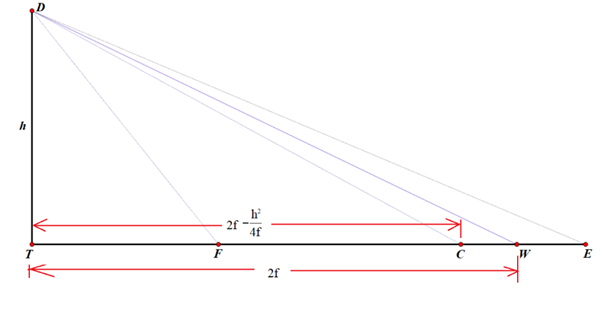
To find the x-coordinate of E, I will employ the tangent of angle TDE.
To make the computations easier, I will draw a couple of simplified diagrams that keep the essentials.


I also tried other approaches, and also got answers that made no sense. It looks like the formula in the 1902 article is correct, but I have not been able to confirm it.
I suspect I made a very stupid and obvious algebra mistake that anybody who has made it through pre-calculus can easily find and point out to me, but I have had no luck in finding it so far. I would love for someone did to point it out to me.
Thanks.
But this still does not answer Tom’s question!


