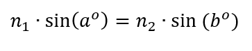
• My series on making a Newtonian telescope
  • How Leon Foucault Made Telescopes

Guy's Math & Astro Blog

Guy's Math & Astro Blog

Category Archives: Math

A neat geometry lesson! And a rant…

13 Thursday Feb 2020

Posted by gfbrandenburg in education, flat, History, Math, Optics, teaching, Telescope Making, Uncategorized

≈ Leave a comment

Tags

apps, computer, computer-managed instruction, geometry, kaleidoscope, Math, Mirror, programs, reflection, school

Here is some information that teachers at quite a few different levels could use* for a really interesting geometry lesson involving reflections involving two or more mirrors, placed at various angles!

Certain specific angles have very special effects, including 90, 72, 60, 45 degrees … But WHY?

This could be done with actual mirrors and a protractor, or with geometry software like Geometer’s Sketchpad or Desmos. Students could also end up making their own kaleidoscopes – either with little bits of colored plastic at the end or else with some sort of a wide-angle lens. (You can find many easy directions online for doing just that; some kits are a lot more optically perfect than others, but I don’t think I’ve even seen a kaleidoscope that had its mirrors set at any angle other than 60 degrees!)

I am reproducing a couple of the images and text that Angel Gilding provides on their website (which they set up to sell silvering kits (about which I’ve posted before, and which I am going to attempt using pretty soon)).

At 72º you see 4 complete reflections.

When two mirrors are parallel to each other, the number of reflections is infinite. Placing one mirror at a slight angle causes the reflections to curve.


https://angelgilding.com/multiple-reflections/

===========

Rant, in the form of a long footnote:

* assuming that the teacher are still allowed to initiate and carry out interesting projects for their students to use, and aren’t forced to follow a scripted curriculum. It would be a lot better use of computers than forcing kids to painfully walk through (and cheat, and goof off a lot) when an entire class is forced to use one of those very expensive but basically worthless highly-centralized, district-purchased computer-managed-instruction apps. God, what a waste of time – from personal experience attempting to be a volunteer community math tutor at such a school, and also from my experience as a paid or volunteer tutor in helping many many students who have had to use such programs as homework. Also when I was required to use them in my own classes, over a decade ago, I and most of my colleagues found them a waste of time. (Not all – I got officially reprimanded for telling my department chair that ‘Renaissance Math’ was either a ‘pile of crap’ or a ‘pile of shit’ to my then-department head, in the hearing of one of the APs, on a teacher-only day.

Keep in mind: I’m no Luddite! I realized early on that in math, science, and art, computers would be very, very useful. I learned how to write programs in BASIC on one of the very first time-share networks, 45 years ago. For the first ten years that my school system there was almost no decent useful software for math teachers to use with their classes unless you had AppleII computers. We had Commodore-64’s which were totally incompatible and there were very few companies (Sunburst was one) putting out any decent software for the latter. So when I saw some great ideas that would be ideal for kids to use on computers to make thinking about numbers, graphs, and equations actually fun and mentally engaging, often I would have to write them my self during whatever free time I could catch, at nights and weekends. Of course, doing this while being a daddy to 2 kids, and still trying to teach JHS math to a full load of students (100 to 150 different kids a day at Francis Junior High School) and running a school math club and later coaching soccer. (I won’t say I was a perfect person or a perfect teacher. I believe I learned to give better math explanations than most, didn’t believe that you either have a ‘m,ath gene’ or you don’t, at times had some interesting projects, and at times was very patient and clear, but had a terrible temper and often not good at defusing things. Ask my kids or my former students!) Later on, I collaborated with some French math teachers and a computer programmer to try to make an app/program called Geometrix for American geometry classes that was supposed to help kids figure out how to make all sorts of geometric constructions and then develop a proof of some property of that situation. It was a failure. I was the one writing the American version, including constructions and tasks from the text I was currently using. There was no way I could anticipate what sorts of obstacles students would find when using this program, until I had actual guinea pig students to use them with. Turns out the final crunch of writing however many hundreds of exercises took place over the summer, and no students to try them on. Figuring out hints and clues would require watching a whole bunch of kids and seeing what they were getting right or wrong. In other words, a lot of people’s full time job for a long time, maybe paying the kids as well to try it out so as to get good feedback, and so on. Maybe it could work, but it would require a lot more investment of resources that the tiny French and American companies involved could afford. We would have really needed a team of people, not just me and a single checker.

I find that none of these computer-dominated online learning programs (much less the one I worked on) can take the place of a good teacher. Being in class, listening to and communicating logically or emotionally with a number of other students and a knowledgeable adult or two, is in itself an extremely important skill  to learn. It’s also the best way to absorb new material in a way that will make sense and be added to one’s store of knowledge. That sort of group interaction is simply IMPOSSIBLE in a class where everybody is completely atomized and is on their own electronic device, engaged or not.

Without a human being trying to make sense out of the material, what I found quite consistently, in all the computerized settings, that most students absorbed nothing at all or else the wrong lessons altogether (such as, ‘if you randomly try all the multiple choice answers, you’ll eventually pick the right one and you can move on to some other stupid screen’; it doesn’t matter that all your prior choices were wrong; sometimes you get lucky and pick the right one first or second! Whee! It’s like a slot machine at a casino!).

By contrast, I found that with programs/apps/languages like Logo, Darts, Green Globs, or Geometer’s Sketchpad, with teacher guidance, students actually got engaged in the process, had fun, and learned something.

I find the canned computer “explanations” are almost always ignored by the students, and are sometimes flat-out wrong. Other times, although they may be mathematically correct, they assume either way too much or way too little, or else are just plain confusing. I have yet to detect much of any learning going on because of those programs.

Silvering Mirrors, and More, at Stellafane

05 Monday Aug 2019

Posted by gfbrandenburg in astronomy, flat, History, Math, monochromatic, optical flat, Optics, science, teaching, Telescope Making, Uncategorized

≈ 3 Comments

For me, these were the two most significant demos at the 2019 Stellafane Convention in Springfield, Vermont:

(1) Silvering large mirrors, no vacuum needed

We had a demonstration by Peter Pekurar on how to apply a layer of Silver (metallic Ag, not aluminum) onto a telescope mirror, accurately, with a protective, non-tarnishing overcoat, that works well. I looked through such a scope; the view was quite good, and I was told that interferograms are great also.

What’s more, the process involves overcoating a mirror with spray bottles of the reagents, without any vacuum apparatus needed at all. Note: Silver coated, not aluminum coated. This is big for me because the upper limit at our club’s aluminizer is 12.5″, but some of us are working on larger mirrors than that; commercial coaters currently charge many hundreds of dollars to coat them.

You can find information on some of these materials at Angel Gilding. Peter P said he will have an article out in not too long. Here are a few photos and videos of the process:

IMG_4972

Finished mirror; notice it’s a little blotchy


IMG_4978

IMG_4978


IMG_4981

IMG_4981

IMG_4985IMG_4987

(2) Demo and links for Bath Interferometer (see http://gr5.org/bath )

How to set up and use a Bath interferometer to produce highly accurate interferograms of any mirror for many orders of magnitude less cash than a Zygo interferometer. As I wrote earlier, Alan Tarica had taken the lead on fabricating one at the CCCC – NCA ATM workshop, and we eventually got it to work, but found it rather frustrating and fiddly to use.

The presenter is a HS teacher, and it shows: he explains things very clearly! On his website ( http://gr5.org/bath ) you can get plans for 3-D printing the parts for the Bath device, if you have any access to a 3-D printer, so you can print the parts out for yourself. He also has links to vendors that are selling parts for it, such as certain small lenses, mirrors and beam splitters. He shows you where you can get them for very little money from Surplus Shed and such places. Or you can purchase his really inexpensive kits that he’s already 3-D printed for you. Plus parts for an XYZ stage, which you will need for fine focus. The whole setup (not counting mirror stand and two tripods, which he assumes you have access to already) is under $130.

I will need to look carefully at our setup as built almost completely by Alan, and see how it differs and what we would need to do to make it better. The problem is that there are lots of little, tiny parts, and many of them need to be adjustable. We saw him doing LOTS of little adjustments!

Before his talk, I had absolutely no idea how this (or similar interformeters) really worked. Now I understand: the interference fringes that we see are really contour lines – like we see on on a USGS topo map, only with the mirror tilted in one direction or the other. A big difference with the USGS topo map is that there, the contour lines (isohypses – a new word for me today) are often 10 feet to 100 meters apart. In interferometry, the contour intervals are either one or one-half lambda (wavelength of light) apart – a really tiny amount! We need that level of accuracy because the surface we are studying is sooooooo flat that no other measuring system can work. His explanation of this whole thing now makes perfect sense to me. And the purpose of the software (free!) is to un-slant the mirror and re-draw it using the countour-line information.

Beautifully clear explanation!

Caution: a friend who works professionally in optics told me his team had made three Bath interferometers, using cheap but good quality ebay xyz stages, and found that they were just too much trouble; so they borrowed a very expensive commercial interferometer (costing many tens of kilobucks) from another department and are using that instead. I’m not selling my house to get a Zygo interferometer!!! But I will try the Bath interferometer instead.


Why Not Show Students the Beauty of Math?

16 Tuesday Oct 2018

Posted by gfbrandenburg in education, Math, teaching

≈ Leave a comment

Tags

algebra 2, algebra two, beauty, benoit mandelbrot, complex numbers, education, imaginary numbers, julia set, mandelbrot set, Math, strange, weird

When I taught math, I tried to get students to see both the usefulness and beauty of whatever topic we were discussing. The most beautiful mathematical objects I know of are the Mandelbrot and Julia sets, which in my opinion should be brought up whenever one is studying imaginary and complex numbers.

To illustrate what I mean, here are some blown up pieces of the Mandelbrot set. Below,  I’ll explain the very simple algebra that goes into making it.


I made these images using an app called FastFractal on my iPhone. The math goes like this:

Normally, you can’t take the square root of a negative number. But let’s pretend that you can, and that the square root of negative one is the imaginary number i. So the square root of -16 is 4i. Furthermore, we can invent complex numbers that have a real part like 2, or 3.1416, or -25/17, or anything else, and an imaginary part like 3i or -0.25i. So 2-3i is a complex number.

Ok so far?

We can add, subtract, multiply and divide real, imaginary and complex numbers if we want, just remembering that we need to add and subtract like terms, so 4+3i cannot be simplified to 7i; it’s already as simple as it gets. Remember that i multiplied by i gives you negative one!

Interesting fact: if you multiply a complex number (say, 4+3i) by its conjugate (namely 4-3i) you get a strictly REAL answer: 25! (Try it, using FOIL if you need to, and remember that i*i=-1!)

Furthermore, let us now pretend that we can place complex numbers on something that looks just like the familiar x-y coordinate plane, only now the x-axis becomes the real axis and the y-axis becomes the imaginary axis. So our complex number 4+3i is located where the Cartesian point (4, 3) would be.

Ok — but what’s the connection to those pretty pictures?

It’s coming, I promise!

Here’s the connection: take any point on the complex plane, in other words, any complex number you wish. Call it z. Then:

(1) Square it.

(2) Add the original complex number z to that result.

(3) See how far the result is from the origin.

(4) Repeat steps 1 – 3 a whole lot of times, always adding the original z.

One of two things will happen:

(A) your result stays close to the origin, OR

(B) it will go far, far away from the origin.

If it stays close to the origin, color the original point black.

If it gets far away, pick some other color.

Then repeat steps 1-4 for the point “right next” to your original complex point z. (Obviously, the phrase “right next to” depends on the scale you are using for your graph, but you probably want fine coverage.)

When you are done, print your picture!

If we start with 4+3i, after one round I get 11+27i. After two rounds I get -604 + 597i, which is very far from the origin, so I’m going to stop here and color it blue. I’ll also decide that every time a result gets into the hundreds after merely two rounds, that point will also be blue.

Now let’s try a complex point much closer to the origin: how about 0.2+0.4i? I tried that a bunch of times and the result seems to converge on about 0.024+0.420i — so I’ll color that point black.

This whole process would of course be very, very tedious to do by hand, but it’s pretty easy to program a graphing calculator to do this for you.

When Benoit Mandelbrot and others first did this set of computations in 1978-1980, and printed the results, they were amazed at its complexity and strange beauty: the border between the points we color black and those we color otherwise is unbelievably complicated, even when you zoom in really, really close. Who woulda thunk that a simple operation with complex numbers, that any high school student in Algebra 2 can do and perform, could produce something so beautiful and weird?

So, why not take a little time in Algebra 2 and have students explore the Mandelbrot set and it’s sister the Julia set? They might just get the idea that math is beautiful!!!

IMG_1735

Math – How Come We Forget So Much of What We Learned in School?

27 Monday Aug 2018

Posted by gfbrandenburg in astrophysics, education, History, Math, science, teaching, Telescope Making, Uncategorized

≈ Leave a comment

Tags

education, engineering, forgetting, France, mathematics, scientists, USA

This was a question on  Quora. Here is an answer I wrote:

In the US, judging strictly on what I’ve seen from my time in the classroom as both a student, a teacher, and a visiting mentor of other math teachers, I find that math and science was very often taught as sort of cookbook recipes without any real depth of understanding. The recent National Council of Teachers of Mathematics prescriptions have attempted to correct that, but results have been mixed, and the Common Core has ironically fostered a weird mix of conceptual math marred by teachers being *OBLIGATED* to follow a script, word-for-word, if they want to remain employed. Obviously, if students are really trying to understand WHY a certain mathematical or scientific thing/fact/theorem/theory/law is true, they are going to have questions, and it’s obviously the teacher’s job to figure out how best to answer said questions — which are not likely to have pre-formulated scripts to follow in case they come up — and which are going to take time.

Another thing that is true is that not everything in mathematics has real-world applications in every single person’s life. I taught a good bit of computer programming (aka ‘coding’ today), geometry, arithmetic, probability, algebra, statistics, and conic sections, and in fact I use a LOT of that every week fabricating telescope mirrors to amazing levels of precision, by hand, not for a living, but because I find telescope-making to be a lot of fun and good mental, aesthetic, manual, and physical exercise. But I’m a pretty rare exception!

Most people obviously don’t dabble in math and physics and optics like I do, nor should they!

In fact, I have made it a point to ask professional scientists and engineers that I meet if they actually use, on their jobs, all the calculus that they learned back in HS and college. So far, I think my count is several dozen “Noes” and only one definite “Yes” – and the latter was an actual rocket scientist / engineer and MIT grad and pro-am astronomer (and wonderful, funny, smart person) who deals/dealt with orbital rocket trajectories. (IIRC).

In France, when I went to school there 50 years ago and in my experience tutoring some kids at the fully-French Lycee Rochambeau near Washington, DC, is that they go very deeply into various topics in math, and the sequence of topics is very carefully thought out for each year for each kid in the entire nation (with varying levels of depth depending on what sort of track that the students elected to go into (say, languages/literature, pure math, or applied sciences, etc), but the kids were essentially obligated to accept certain ideas as factual givens and then work out more and more difficult problems that dealt with those particular givens. No questions allowed on where the givens came from, except to note the name of the long-dead classical Greek, French, Italian or German savant whose name is associated with it.

As an American kid who was mostly taught in American schools, but who also took 2 full years of the French system (half a year each of neuvieme, septieme, premiere, terminale, and then passed the baccalaureat in what they called at the time mathematiques elementaires, I found the choice of topics [eg ‘casting out nines’ and barycenters and non-orthogonal coordinate systems] in France rather strange. Interesting topics perhaps, but strange. And not necessarily any more related to the real world than what we teach here in the US.

Over in France, however, intellectuals are (mostly) respected, even revered, and of all the various academic strands, pure math has the highest level of respect. So people over there tend to be proud of however far they got in mathematics, and what they remember. Discourse in French tends to be extremely logical and clear in a way that I cannot imagine happening here in the public sphere.

So to sum up:

(a) most people never learned all that much math better than what was required to pass the test;

(b) only a very few geeky students like myself were motivated to ask ‘why’;

(c) most people don’t use all that much math in their real lives in the first place.


Quantifying Progress in the Fight Against Turned Down Edge

27 Tuesday Mar 2018

Posted by gfbrandenburg in astronomy, Math, Optics, Telescope Making, Uncategorized

≈ Leave a comment

Tags

Applebaum, Mel Bartels, Ronchi

By Guy Brandenburg

3/27/2017

I describe here an attempt to quantify progress (or lack thereof) in the removal of the classic, and dreaded, turned-down edge (TDE) present on a 16.5” Newtonian glass mirror blank that I have been trying to “figure” for some years.  The figuring process means changing a piece of glass that approximates a small section sliced out of a large hollow sphere, into a highly-accurate paraboloid — with the required level of accuracy being measured in nanometers.


Many amateur and professional telescope makers have maintained that you can only fix figuring errors if you can measure them. Not being able to get good, repeatable measurements of the TDE on my mirror, I had been sort of floundering, failing to get rid of the TDE even after YEARS of work (off and on; mostly off). So a decision was made to try to quantify things.


We recently had some success in matching computer-generated Ronchi images of theoretically-perfect mirrors with photos taken of works in progress, simply by cutting and pasting – which has been recommended by Mel Bartels in particular for quite some time. For the first time, I got the hang of it, and we were able to help a first-timer (Mike L) to figure a 10” plate glass f/5.4 mirror only ¾” thick to just about exactly ¼ lambda, according to our combined, repeated, careful measurements on a mirror that was cooled both by immersion in a room-temperature water bath and by sitting in a closet in the very same testing room for an entire weekend.


Prior to this experiment, I had been taking short videos of the entire mirror, moving the ronchi grating back and forth across the center of curvature. These videos reveal and record a lot of qualitative information about the mirror, including vocal commentary, but I found it impossible to transfer the images to my laptop for closer analysis until I got home, across town, which meant that the turn-around time after testing a mirror was much too long to be of any use. I had tried quite a large number of various strokes suggested by others, by our reading various ATM manuals, and by just thinking; but the very serious TDE on this (for me, relatively ambitious) project never seemed to get any better.


I simply gave up on imaging via video clips, since they were too hard to manipulate or measure on my phone, and which required too much bandwidth to send to my laptop until I got home. This time, I took Ronchi still-images on my cell phone, between 0.2 and 0.5 inches outside of the center of curvature.

guys 16 perfect

(My experience has been generally easier to discern defects in a Ronchigram when the lines curve outwards at the top and bottom, which would mean the test grating is  OUTSIDE the COC of a partly-parabolized mirror, as you see on the left in the black-and-white image above. However, when the lines curve inwards at the top and bottom, like the images in the center and to the right, then many serious defects remain hidden. quantify TDE

Procedure:

A standard 100 LPI grating from Willmann-Bell and a yellow LED were used, on an XYZ stage partly fabricated by me and placed exactly twice the focal length from the primary. Images were taken with an iPhone 6, shooting images zoomed in as much as possible. An attempt was made to have matching ronchigrams, i.e., with the same number of vertical lines showing.


(This was a weak point of the experiment. For one, it’s hard to hold cell phone steady enough, and an observer will notice that the images do NOT have exactly the same number of lines. That’s because I did not have a printout of the previous image right in front of me to make comparisons to. All that needs to be fixed in subsequent iterations. Also, other imaging devices need to be tried, as well.)


I was in fact able to email individual photograph frames to my laptop at the lab. After downloading the clearest images to my laptop, I used plain old MS Windows Paint to shrink and crop the useful portion of the picture, and then pasted the result into a Geometry software (Geometer.s Sketchpad, or GSP) that I was already familiar with. GSP was then used to draw a circle around the circumference of the image of the nearly-perfectly-circular glass disk, adjusting this as well as possible. This process automatically generated the center of the disk. Using that center, a second, and smaller, circle was drawn whose circumference was placed at the location along the ronchi lines where they appeared to begin to turn outwards. GSP was then  to measure directly the radii of the two circles and to compute their ratio.


A final ratio of 0.7, just to pick a number that is easy to compute, means that just about half of the area of the mirror is covered by a wide rolled-down edge, since the ratio of areas is equal to the square of the ratio of the respective radii, and 0.7 squared is 0.49, or 49%.


In the diagram above, the images go in chronological order but COUNTER-clockwise, from upper left (labeled #1), which was made in mid- or early March, through the next three images, all taken on March 22. In between each image, various strokes were employed in figuring sessions for anywhere between 15-20 minutes to attempt to fix the TDE. All the figuring sessions involved sub-diameter laps anywhere from 8 to 12 inches in diameter that had been warm-pressed upon the mirror. The strokes were both forward and back and incorporated enough of a ‘W’ stroke to cover the entire mirror, using cerium oxide on either tempered burgundy or Acculap pitch, depending. The edge of the tool was allowed to go up to the edge of the mirror, +/- maybe 5 mm. The goal was simply to wear down the glass in the center until it caught up with the amount that the edge had been worn down. None of the laps seemed to have full contact with the mirror out to the very edge; thus the end of the stroke was NOT at the edge of the mirror.


You will notice that these ratios, circled in green, seem to increase monotonically from 69% to 80%, which is gratifying: if this real, then the fraction of the mirror that is NOT covered by TDE has gone from about 47% to about 67%, as you can see here. (Note: in figure #1, the large circle was denoted circle AB, and the smaller circle was denoted circle CD. I know that points A and C are not identical, but they are rather close; that error will be fixed in subsequent iterations.)

However: the key question is: IS THIS REAL? Or am I merely fooling myself?

I don’t know yet.

I certainly hope it is real.

But it needs to be checked with subsequent investigation.

My attempt at limiting my own subjectivity or wishful thinking was to try to draw the circles at the place where the more-or-less vertical lines began turning outwards. Hopefully that location really corresponded to the place where the turned/rolled edge began. However, it is entirely possible that the precise apparent location of the beginning of the TDE very much depends on exactly how many lines appear in the Ronchigram, thus, precisely how far from the COC the grating is located.

Unfortunately, often times I have to dismantle the entire apparatus, because we have to close up shop for the night, or somebody else needs to use the tester on another mirror. Thus, it is nearly impossible to ensure that the measurement apparatus remains undisturbed.

My next steps, I think, are these:

  1. Have a separate, and very simple ronchi apparatus that just consists of a grating and a light.
  2. Have previous images right in front of me as I prepare to take the next Ronchigrams, so that I can match the number of lines visible.
  3. Perhaps I should take a series of said standardized ronchigrams both inside and outside of COC with, say, 5 lines visible. I should also take some ronchigrams that might accentuate and expose any possible astigmatism; that is, very close to the COC. Any Ronchi lines that resemble the letters S, Z, J, U, or N would be very bad news.
  4. Attempt to attach a cheap video camera with built-in LED, Ronchi grating, and a suitable lens to make steadier images free from hand wobbles.

I would like to thank Isaac and Elias Applebaum for their diligent and noted explorations in solving a similar question relating to fixing or preventing TDE. That STEM project won them a number of well-deserved awards.


A 6″ Dob for Young Relatives

31 Wednesday Jan 2018

Posted by gfbrandenburg in astronomy, Math, Optics, Telescope Making, Uncategorized

≈ Leave a comment

I just finished a 6″ f/8 Dobsonian telescope as a gift for my great-nephews, one of whom I discovered is VERY interested in astronomy and happens to live in a place with pretty dark skies – about the middle of Maryland’s Eastern Shore. The mirror is excellent, and the mechanical parts all work very well — in my opinion. Let’s see what the recipients think.

I finally succeeded in putting in the mirror yesterday afternoon in a very stiff and cold wind right outside my house, estimating where the mirror should go by aiming at a distant chimney. This takes patience because it’s trial-and-error, no matter how much you calculate beforehand!

Later that evening, after the nearly-full Blue Moon came over the trees at DC’s Chevy Chase Community Center where we have our telescope-making classes, fellow ATMer and all-around interesting person Jim Kaiser helped me collimate it by pointing the scope at the illuminated curtains in the windows of the CCCC. We then verified that the Moon actually did come to a focus with the eyepiece nearly all the way screwed in. If you want to focus on closer things than the Moon or galaxies, you need to screw the eyepiece out towards you, the observer in the cheap but effective helical focuser that was lying around the shop.

This scope incorporates a couple of innovations by me, and a bit of artistic whimsy.

First small innovation: I made the secondary diagonal mirror holder so that no tools are needed at all: you just rotate the part holding the elliptical mirror and turn a little thumbscrew to collimate it quickly and easily, while you watch. Here is a sketch of how I made it.new type of secondary holder


Second innovation can be seen near my right hand (to your left) atop the cradle: two 1/4″-20 machine screws with simple homemade knobs on top, going through threaded inserts (T-nuts would work too), which push against a piece of lumber in the shape of prism with an isosceles right triangle at each end. I call this the tube brake, which can be applied or released quite easily, whenever needed. Small springs (almost impossible to see in this photo) pull this brake up against the corner of the tube, while the machine screws press it down. If you want to change the position of the eyepiece because a taller or shorter person has arrived, no problem. A few CCW turns of the wooden knobs releases the brake, you rotate the tube to the desired position, and then you lock it down again with a few clockwise turns. If you add or remove a heavy eyepiece or a finder or whatever, same procedure, except this time you can slide the scope up and down inside the cradle.

The artistic whimsy is partly seen in a photo Jim took of me after we got it collimated but before we rushed back inside: lots of colors, thanks to several tons of paint cans salvaged by fellow ATMer Bill Rohrer from being thrown away by a third party who lost his warehouse lease, and also because smurf blue is the favorite color of one of the boys. The altitude bearing is made out of the Corian countertop that my wife and I got rid of a few months ago when we had our kitchen remodeled. (30 years ago we did it ourselves, mostly. This time we hired professionals. They are SOO much faster and better at this than us!)

So that my young relatives can keep this thing looking good, they also get four or five quart or pint cans of paint – the ones I used on the scope. Free, of course. The more we get rid of put to use, the better. They can repaint anything that gets scratched, you see?IMG_9416

You can also see some wood-cutting fun above and below. This retired geometry teacher had a lot of fun figuring out how to lay out and cut out stars with 5, 6, and 7 points, as well as a crescent moon and a representation of Saturn seen with its rings edge-on. I guess you could show Saturn’s rings a 30 to 45 degrees to the viewer, if you instead carved it out of solid wood or did wood burning, but I just had a hand-held jigsaw and a Dremel knockoff. And plus, this is supposed to be a scope that is USED rather than just admired for its artsy parts.

I designed what I wanted onto two sheets of paper and then taped them to the plywood. This worked, but it wasn’t the most wonderful plywood, so on many of the pull strokes, the wood splintered a bit. So that side got to face inside.. Painting all those little nooks and crannies was tough!

design artsy astro cutouts

(The purpose of the cut-outs was simply to make the telescope lighter. It’s got a very heavy and sturdy base. Each square inch of plywood removed saves about 7 grams. Also, more holes means more hand-holds!)


Trying to Test a 50-year-old Cassegran Telescope

07 Thursday Sep 2017

Posted by gfbrandenburg in astronomy, flat, Hopewell Observatorry, Math, science, Telescope Making

≈ Leave a comment

Tags

artificial star, celestron, classical cassegrain, couder, double pass autocollimation test, ealing, FigureXP, focus, foucault, hyperbolic, optical tube assembly, parabolic, primary, refurbishing, ritchey-chretien, Ronchi, schmidt-cassegrain, secondary, spherical, Telescope

We at the Hopewell Observatory have had a classical 12″ Cassegrain optical tube and optics that were manufactured about 50 years ago.; They were originally mounted on an Ealing mount for the University of Maryland, but UMd at some point discarded it, and the whole setup eventually made its way to us (long before my time with the observatory).


The optics were seen by my predecessors as being very disappointing. At one point, a cardboard mask was made to reduce the optics to about a 10″ diameter, but that apparently didn’t help much. The OTA was replaced with an orange-tube Celestron 14″ Schmidt-Cassegrain telescope on the same extremely-beefy Ealing mount, and it all works reasonably well.


Recently, I was asked to check out the optics on this original classical Cassegrain telescope, which is supposed to have a parabolic primary and a hyperbolic secondary. I did Ronchi testing, Couder-Foucault zonal testing, and double-pass autocollimation testing, and I found that the primary is way over-corrected, veering into hyperbolic territory. In fact, Figure XP claims that the conic section of best fit has a Schwartzschild constant of about -1.1, but if it is supposed to be parabolic, then it has a wavefront error of about 5/9, which is not good at all.

Here are the results of the testing, if you care to look. The first graph was produced by a program called FigureXP from my six sets of readings:

figure xp on the 12 inch cass

my graph of 12 inch cass readings

I have not yet tested the secondary or been successful at running a test of the whole telescope with an artificial star. For the indoor star test, it appears that it only comes to a focus maybe a meter or two behind the primary! Unfortunately, the Chevy Chase Community Center where we have our workshop closes up tight by 10 pm on weekdays and the staff starts reminding us of that at about 9:15 pm. Setting up the entire indoor star-testing rig, which involves both red and green lasers bouncing off known optical flat mirrors seven times across a 60-foot-long room in order to get sufficient separation for a valid star test, and moving two very heavy tables into said room, and then putting it all away when we are done, because all sorts of other activities take place in that room. So we ran out of time on Tuesday the 5th.

A couple of people (including Michael Chesnes and Dave Groski) have suggested that this might not be a ‘classical Cassegrain’ – which is a telescope that has a concave, parabolic primary mirror and a convex, hyperbolic secondary. Instead, it might be intended to be a Ritchey-Chretien, which has both mirrors hyperbolic. We have not tried removing the secondary yet, and testing it involves finding a known spherical mirror and cutting a hole in its center, and aligning both mirrors so that the hyperboloid and the sphere have the exact same center. (You may recall that hyperboloids have two focal points, much like ellipses do.)

Here is a diagram and explanation of that test, by Vladimir Sacek at http://www.telescope-optics.net/hindle_sphere_test.htm

hindle sphere test

FIGURE 56: The Hindle sphere test setup: light source is at the far focus (FF) of the convex surface of the radius of curvature RC and eccentricity ε, and Hindle sphere center of curvature coincides with its near focus (NF). Far focus is at a distance A=RC/(1-ε) from convex surface, and the radius of curvature (RS) of the Hindle sphere is a sum of the mirror separation and near focus (NF) distance (absolute values), with the latter given by B=RC/(1+ε). Thus, the mirrorseparation equals RS-B. The only requirement for the sphere radius of curvature RS is to be sufficiently smaller than the sum of near and far focus distance to make the final focus accessible. Needed minimum sphere diameter is larger than the effective test surface diameter by a factor of RS/B. Clearly, Hindle test is limited to surfaces with usable far focus, which eliminates sphere (ε=0, near and far focus coinciding), prolate ellipsoids (1>ε>0, near and far foci on the same, concave side of the surface), paraboloid (ε=1, far focus at infinity) and hyperboloids close enough to a paraboloid to result in an impractically distant far focus.

We discovered that the telescope had a very interesting DC motor – cum – potentiometer assembly to help in moving the secondary mirror in and out, for focusing and such. We know that it’s a 12-volt DC motor, but have not yet had luck tracking down any specifications on that motor from the company that is the legatee of the original manufacturer.

Here are some images of that part:

IMG_8207
IMG_8210
IMG_8224

An Eclipse Seen in Wyoming

27 Sunday Aug 2017

Posted by gfbrandenburg in astronomy, astrophysics, Math, nature, Telescope Making

≈ Leave a comment

Tags

eclipse, Lander, luggage, Math, solar, sunspots, totality, travel, Wind River Indian Reservation, Wyoming

I was fortunate enough to have the time and cash to go to Wyoming for the August 21 eclipse. It was truly wonderful,. in large part due to the fact that I had made a 6″ diameter, f/8 Dob-Newt travel telescope that could play three roles: as an unfiltered projection scope onto a manila folder before and after totality; with a stopped-down Baader solar filter during and after totality; and with no filter at all during the two minutes or so of totality.

No photographic image that I have so far seen comes anywhere near the incredible details that I was able to see during those short two minutes.

Here is my not-very-expert drawing of what I recall seeing:

solar eclipse

The red rim on the upper left is the ‘flash spectrum’, or chromosphere. It was only visible for a few seconds at the very beginning of the eclipse. The corona is the white fuzzy lines, but my drawing doesn’t do them justice. On the bottom, and on the right, are some amazing solar prominences — something that I don’t recall having seen in 1994, my first successful solar eclipse. The bottom one might not have been quite that large, but it really got my attention.

Here are a few photos I took before and after totality:

IMG_8070
IMG_8082
IMG_8091
IMG_8099
IMG_8105
IMG_8108
IMG_8114
IMG_8118
IMG_8120
IMG_8130
IMG_8138
IMG_8140
IMG_8141

I started planning this expedition over a year ago, and hoped to attend the Astronomical League meeting in Casper, WY. I quickly found that there were absolutely no rooms to be had there, even a year in advance.

Wyoming has fewer people than my home town (Washington DC), and not many populated places in the path of totality. However, I did find a motel in tiny Lander, Wyoming, very close to the southern edge — a location that I had previously found to be very good for viewing eclipses. One of the fellows in our telescope-making workshop, Oscar O (an actual PhD solar astrophysicist) decided he would bring some family and friends along and camp there to view it with me. So he did (see the group photo).

The night before, we went to a site near Fossil Hill, WY to look at stars. The Milky Way was amazing, stretching from northern to southern horizon, and the sky was very, very dark. We met a baking-soda miner (actually, a trona miner) and his 10-year-old daughter; she had a great time aiming my telescope, via Telrad, at interesting formations in the Milky Way. My friends from DC whipped up an amazing dinner on their tiny camp stove. There were LOTS of people camping in the back country there; I bet most of them were there to view the eclipse!

On the eve and morning of the eclipse, after consulting various weather ‘products’, we decided that the predicted clouds in Lander itself would be a problem. (I had been clouded out before, with my wife and children, back in 1991, in Mexico! It really spoils the experience, I assure you!)

So we drove north and west, through the Wind River Indian Reservation, and picked a spot just east of the tiny town of Dubois at a pulloff for a local fish hatchery. Along the drive to that location, we saw lots of folks had set up camp for the event at various pulloffs and driveways to nowhere. (If you didn’t know, Wyoming is mostly devoid of people, but has lots of fields and barbed wire fence. Many of those fields have driveways leading to some sort of gate, most of which are probably used at least three times every decade, if you get my drift….)

Not only is Wyoming largely empty (of people), but the path of totality in the United States was so long that I estimated that if the ENTIRE population of the USA were to decide to go view the eclipse, and somehow could magically spread themselves out evenly over the 70-mile-wide, and 3000-mile-long, path on dry land, that there would only be about 3 people per acre!

Here’s the math: 70 miles times 3000 miles is 210,000 square miles. The population of the USA is about 330,000,000. Divide the population by the area, and you get about 1600 people per square mile. But there are 640 acres in a square mile, so if you divide 1600 by 640, you get less than 3 people per acre, or 3 people on a football field (either NFL or FIFA; it doesn’t matter which).

(…looking to the future, the next decent eclipse doesn’t seem to occur anywhere in this hemisphere until 2024, when it will cross from Texas to Maine…)

As you can see from my photos, the little travel scope I made, called Guy’s Penny Tube-O III, performed very well. Before and after totality, we used it both for solar projection onto a manila folder, through the eyepiece. I also had fashioned a stopped-down solar filter with a different piece of cardboard and a small piece of Baader Solar Film. With both methods, we could clearly see a whole slew of sunspots, in great detail (umbra and penumbra) as well as the moon slowly slipping across the disk of the sun. Having the sunspots as ‘landmarks’ helped us to watch the progress!

Then, during totality, after the end of Baily’s Beads and the Diamond Ring, I took off the filter and re-adjusted the focus slightly, and was treated to the most amazing sight – a total eclipse, with coronal streamers to the left and right; the ‘flash spectrum’ appearing and winking out on the upper left-hand quadrant (iirc); and numerous solar flares/prominences.

I got generous and allowed a few other people to look, but only for a few seconds each! Time was precious, and I had spent so much work (and airfare) building, and re-building, and transporting that telescope there!

Planets? I didn’t see any, but others did. Apparently Regulus was right next to the Sun, but I wasn’t paying attention.

The corona and solar flares were much, much more pronounced than I recall from 1994.

That afternoon, the town of Lander had the largest traffic jam they had ever had, according to locals I talked to. Driving out of there on that afternoon was apparently kind of a nightmare: the state had received a million or so visitors, roughly double its normal population, and there just aren’t that many roads. I chose to spend the night in Lander and visited from friends I had gotten to know, who are now living in Boulder, on the night after that. Unfortunately, on that next day, I got a speeding ticket and a citation for reckless driving (I was guilty as hell!) for being too risky and going too fast on route 287, trying to pass a bunch of cars that I thought were going too slow…

When I did fly out from Denver, on Wednesday, all the various inspections of my very-suspicious-looking and very-heavy luggage caused me to miss my flight, so I went on standby. It wasn’t too bad, and I was only a few hours later than I had originally planned. And my lost suitcase was delivered to my door the next day, so that was good.

I am now in the process of making this travel scope lighter. I have removed the roller-skate wheels and replaced them with small posts, saving several pounds. I have begun using a mill to remove a lot of the metal from the struts. And I will also fabricate some sacks that I can fill with local rocks, instead of using the heavy and carefully machined counterweights! (Rocks are free, gut going over 50 pounds in your luggage can be VERY expensive!)


By the way: unless you like to travel with no luggage at all, NEVER use Spirit Airlines! They may be a few dollars cheaper, but they will even charge you for a carry-on bag! What’s next? Charging you for oxygen?


Only 15 Types of Plane-Tiling Convex Pentagons Exist

15 Saturday Jul 2017

Posted by gfbrandenburg in Math

≈ Leave a comment

Tags

geometry, penrose tiling, pentagton, tessellation

It has just been proven that only 15 types of convex pentagons exist that can tile the plane. Which implies that there just might be a single polygon (almost undoubtedly concave) that can tile the plane in a non-periodic manner (as do Penrose tiles; but PTs require two different figures, not a single figure).

(If you’ve ever played with regular pentagons, you have discovered that they can’t tile the plane without gaps or overlapping. The pentagons referred to in this proof are NOT regular. Here is one such example, taken from the article:)

a tessellation with pentagons

You can see many of the details at the following link.


The Mathematics of George Washington

24 Friday Feb 2017

Posted by gfbrandenburg in History, Math, Uncategorized

≈ 2 Comments

Tags

George Washington, History, Math, surveying

I recently learned some things about how the young George Washington did math, including surveying. Mathematician and historian V. Frederick  Rickey gave a talk 2 nights ago at the Mathematical Association of America here in DC, based on his study of GW’s “cypher books”, and I’d like to share a few things I learned.

(1) The young George appears to have used no trigonometry at all when finding areas of plots of land that he surveyed. Instead, he would ‘plat’ it very carefully, on paper, making an accurate scale drawing with the correct angles and lengths, and then would divide it up into triangles on the paper. To find the areas of those triangles, he would use some sort of a right-angle device, found and drew the altitude, and then multiplied half the base times the height (or altitude). No law of cosines or sines as we teach students today.

(2) He was given formulas for the volumes of spheroids and barrels, apparently without any derivation or justification that they were correct, to hold so many gallons of wine or of beer. (You probably wouldn’t guess that you had to leave extra room for the ‘head’ on the beer.) Rickey has not found the original source for those formulas, but using calculus and the identity pi = 22/7, he showed that they were absolutely correct.

(3) GW was a very early adopter of decimals in America.

(4 ) This last one puzzled me quite a bit. It’s supposed to be a protractor, but it only gives approximations to those angles. The results are within 1 degree, which I guess might be OK for some uses. I used the law of cosines to convince myself that they were almost all a little off. Here’s an accurate diagram, with angle measurements, that I made with Geometer’s Sketchpad.

His method was to lay out on paper a segment 60 units long (OB) and then to construct a sixth-of-a-circle with center B, passing through O and G (in green). Then he drew five more arcs, each with its center at O, going through the poitns marked as 10, 20, 30, 40, and 50 units from O. The claim is then that angle ABO would be 10 degrees. It’s not. It’s only 9.56 degrees.

george-washingtons-protractor
← Older posts
Newer posts →

Subscribe

  • Entries (RSS)
  • Comments (RSS)

Archives

  • May 2026
  • April 2026
  • February 2026
  • December 2025
  • November 2025
  • October 2025
  • September 2025
  • July 2025
  • January 2025
  • November 2024
  • October 2024
  • August 2024
  • July 2024
  • May 2024
  • April 2024
  • January 2024
  • December 2023
  • October 2023
  • August 2023
  • June 2023
  • May 2023
  • April 2023
  • November 2022
  • October 2022
  • August 2022
  • July 2022
  • June 2022
  • May 2022
  • April 2022
  • February 2022
  • January 2022
  • December 2021
  • October 2021
  • September 2021
  • August 2021
  • July 2021
  • June 2021
  • May 2021
  • March 2021
  • December 2020
  • October 2020
  • September 2020
  • August 2020
  • March 2020
  • February 2020
  • January 2020
  • December 2019
  • November 2019
  • September 2019
  • August 2019
  • June 2019
  • May 2019
  • January 2019
  • November 2018
  • October 2018
  • September 2018
  • August 2018
  • May 2018
  • March 2018
  • January 2018
  • November 2017
  • October 2017
  • September 2017
  • August 2017
  • July 2017
  • June 2017
  • May 2017
  • April 2017
  • February 2017
  • December 2016
  • September 2016
  • June 2016
  • May 2016
  • April 2016
  • March 2016
  • February 2016
  • January 2016
  • December 2015
  • November 2015
  • August 2015
  • July 2015
  • April 2015
  • March 2015
  • February 2015
  • January 2015
  • December 2014

Categories

  • astronomy
  • astrophysics
  • education
  • flat
  • History
  • Hopewell Observatorry
  • Math
  • monochromatic
  • nature
  • optical flat
  • Optics
  • Safety
  • science
  • teaching
  • Telescope Making
  • Uncategorized

Meta

  • Create account
  • Log in

Blog at WordPress.com.

  • Subscribe Subscribed
    • Guy's Math & Astro Blog
    • Join 54 other subscribers
    • Already have a WordPress.com account? Log in now.
    • Guy's Math & Astro Blog
    • Subscribe Subscribed
    • Sign up
    • Log in
    • Report this content
    • View site in Reader
    • Manage subscriptions
    • Collapse this bar

Loading Comments...