I have made a lot of progress over this winter break in converting the 50-year-old Ealing telescope mount at the Hopewell Observatory, as you can see in this video.
We are swapping out an electro-mechanical “dumb” drive that failed, in favor of a modern, solid-state one built in the Arduino environment. If it all works out as planned, this mount will be able to slew to any target and keep the target steady enough for astrophotograpy. I hope.
With a project like this, with delicate electronics that can easily get fried, I believe that having spare parts on hand is a good idea. The main board is pretty cheap: under $100, completely assembled, and the motors were about $30 each. We have spare stepper motors, spare stepper drivers, and a total of three main MaxESP OnStep boards.
Except that two of them (the ones we purchased from George C) don’t work at all, and I don’t know why. The one that Ken Hunter built and **donated** to us works just fine, after I did the required tweaking of various settings inside the Smart Hand Controller or SHC and inside a CONFIG.H file in the Arduino programming environment. And added the gears and belt.
I see almost no serious differences between George’s boards and Ken’s board. I am confident the problem is not my wiring or soldering, and it’s not the fact that George’s boards have RJ45 jacks, but what it is, I have no idea.
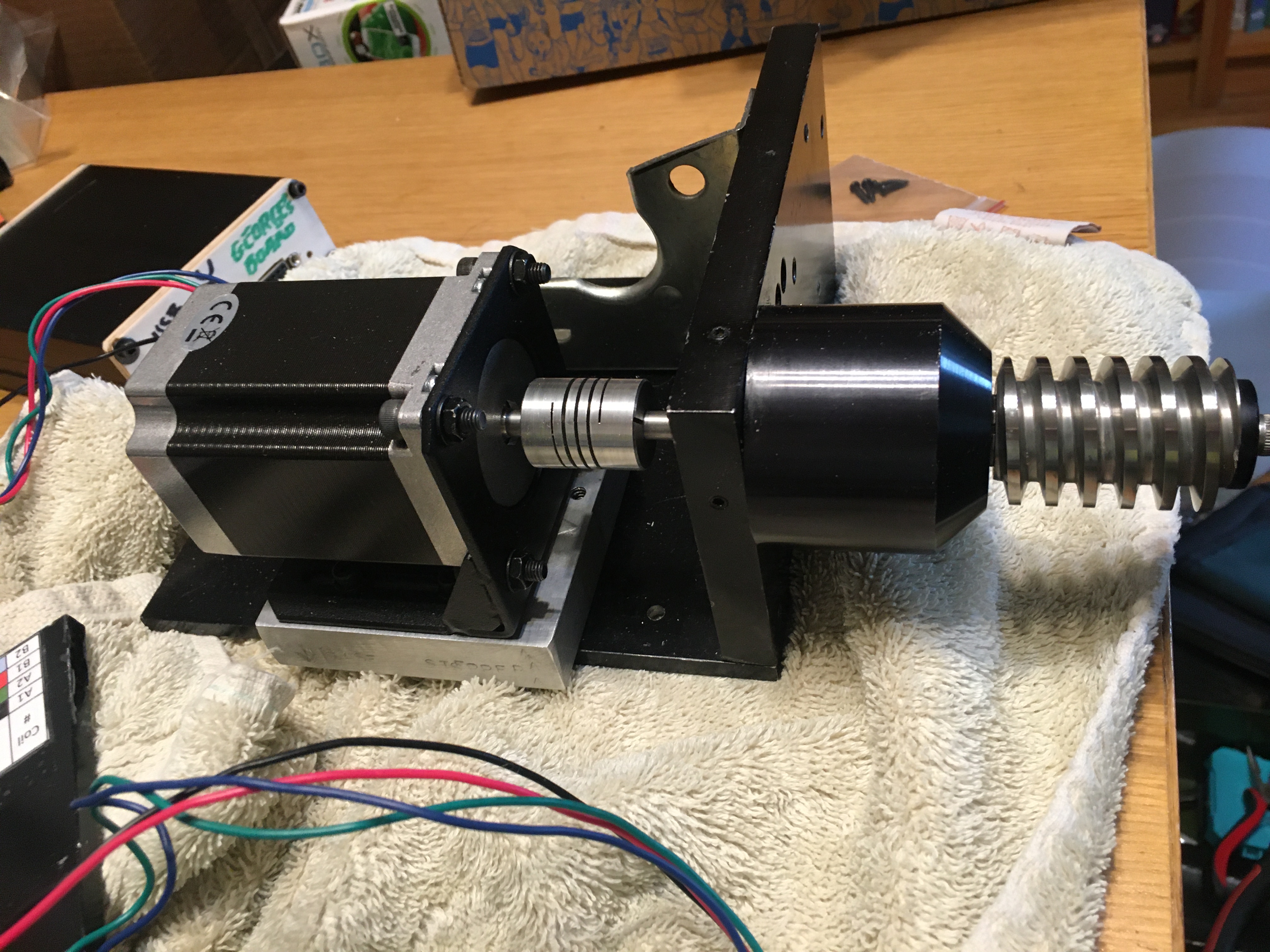
This is my second build of the connections between the stepper motor and the worm gear.
Without the help of Ken H, Howard Dutton, another Ken, Alan Tarica, Prasad Agrahar, and Khaled Bahayeldin, I never would have gotten this far. I am very appreciative of the amount of work that went into programming all of the many parts of the OnStep project as a whole. However, I found the OnStep Wiki rather confusing for beginners, and I hope to help them make it clearer in the future.
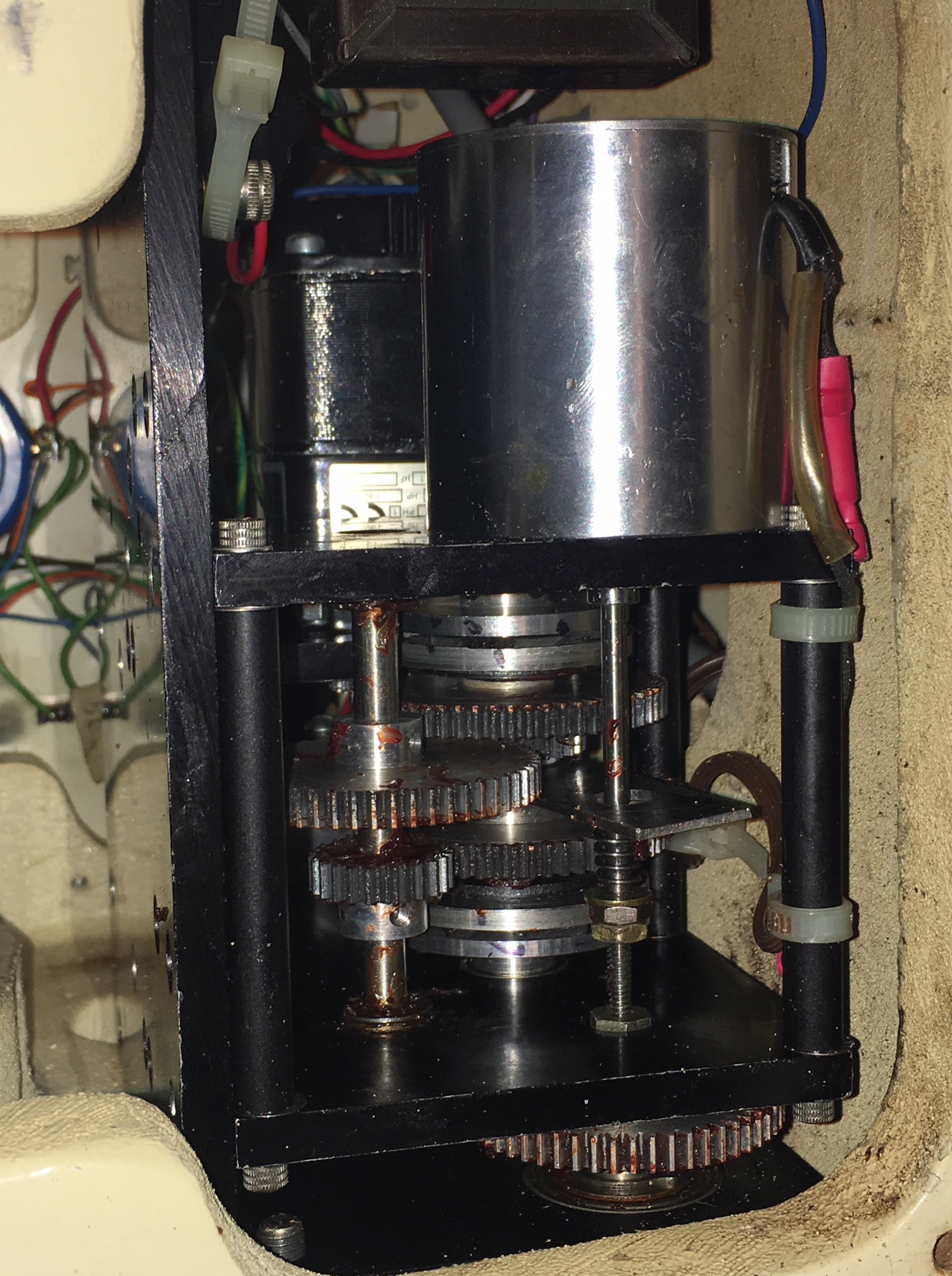
You can probably see that there is a good bit of wobble in the gears that involve the belts. That is probably because I failed to get the gears perfectly flush against the lathe chuck when I was enlarging their central holes from 5 mm to 1/4 inch despite using a dial indicator with a magnetic base to center it. I think I will need to order a new set of gears that have a 1/4″ axle hole already made at the factory. I don’t think I can do any better than I did, and that wasn’t good enough.
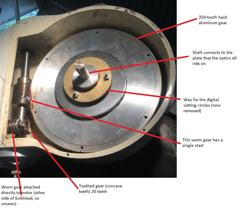
The reason for having the gears and belts is something to do with microstepping on the stepper motors that I really don’t understand. OnStep experts told me that the OnStep board, drivers, and steppers simply cannot handle gears that are 1 : 20 : 359. So we added a 3:1 toothed-gear-and-belt system so that the ratios are now 3 : 1 : 20 : 359. That set of ratios seems to make the steppers happy. (These motors have 200 steps per rotation, and are being currently driven at a rate of 1/16 of a step.) They don’t scream and stall any more, but the wobbly gears will probably translate into periodic error that one can see in the eyepiece or on long exposures with some kind of camera.
My next step is to take this entire apparatus up to the Hopewell Observatory itself and see what happens when I install them in the Right Ascension and Declination drives.
Then, we need to repair the electrical supply for the roll-off roof.
Then we have to put the telescopes back onto the mount.
Then, and only then, can we try having a “First Light” with the new motor pushing a very nice Ed Byers drive in an big, old, and very well-built university-grade telescope mount.