Tags
astronomy, ealing, Ealing mount, Hopewell, Hopewell Observatory, Moon, planet, solar system, Telescope
These were made by Gael Gomez, a recent HS grad who visited on Monday, July 1.


04 Thursday Jul 2024
Posted in astronomy, Hopewell Observatorry
Tags
astronomy, ealing, Ealing mount, Hopewell, Hopewell Observatory, Moon, planet, solar system, Telescope
These were made by Gael Gomez, a recent HS grad who visited on Monday, July 1.
28 Friday Apr 2023
Posted in astronomy, Hopewell Observatorry
Because of the wet weather and clouds predicted for Saturday, April 29, 2023 we are canceling the free, public open house we had planned for tomorrow night — itself a postponement because of the clouds on the previous Saturday.
We will try again in the fall.
This is what the GFS forecast is producing for a forecast of average cloud cover for 8 pm EDT Saturday (00:00 Sunday, Universal Time, aka Zulu time) in the mid-Atlantic sector. White means ‘Overcast’.

15 Saturday Apr 2023
Posted in astronomy, education, Hopewell Observatorry
Come to Bull Run Mountain for a free night under the stars looking at a variety of targets using the telescopes at the Hopewell Observatory on Saturday, April 27, 2024.
You are invited, but will need to RSVP and, in this litigious age, must agree to a waiver of liability for anything that might happen out there in the woods – and they do exist! Plus we don’t have running water — so, we use an outhouse.
Here is the RSVP form: https://hopewellobservatory.rsvpify.com
But if you take the risk you, for free, can view Jupiter and its moons, comet 12P/Pons–Brooks, and a bunch of bright open clusters like the Pleiades, Beehive and Orion star clusters — and a gaggle of galaxies and double stars.
We have a variety of permanently-mounted and portable telescopes of different designs, some commercial and some made by us, some side-by-side, enabling several people to view the same object in the sky with different magnifications.
The date is Saturday, April 27. We suggest arriving near sundown, which will happen near 8 pm. It will get truly dark about an hour later.
There are no street lights near our observatory, other than some dimly illuminated temporary signs we put along the path, so you will probably want to bring a flashlight of some sort.
If you own a scope or binoculars, feel free to bring them!
Hopewell is about 45 minutes by car from where I-66 intersects the DC beltway. The last two miles of road are dirt and gravel, and you will need to walk about 200 meters/yards from where you park. We do have electricity, and a heated cabin, but since we have no running water, we have an outhouse and hand sanitizer instead.
We are located about 30 miles west of the Beltway on Bull Run Mountain – a ridge that overlooks Haymarket VA from an elevation of 1100 feet, near the intersection of I-66 and US-15. Detailed directions are below.
Assuming good weather, you’ll also get to see the Milky Way itself, although not as well as in years past, because of ever-increasing light pollution.
If you like, you can bring a picnic dinner and a blanket or folding chairs, and/or your own telescope binoculars, if you own one and feel like bringing them. We have outside 120VAC power, if you need it for your telescope drive, but you will need your own extension cord and plug strip. If you want to camp out or otherwise stay until dawn, feel free!
If it gets cold, our Operations Building, about 40 meters north of the Observatory itself, is heated, and we will have the makings for tea, cocoa, and coffee.
Warning: While we do have bottled drinking water and electricity and we do have hand sanitizer, we do not have running water; and, our “toilet” is an outhouse of the composting variety. At this time of year, the bothersome insects haven’t really taken off but feel free to use your favorite bug repellent, (we have some) and check yourself for ticks after you get home.
The road up here is partly paved, and partly gravel or dirt. It’s suitable for any car except those with really low clearance, so leave your fancy sports car (if any) at home. Consider car-pooling, because we don’t have huge parking lots.
Two of our telescope mounts are permanently installed in the observatory under a roll-off roof. One is a high-end Astro-Physics mount with a 14” Schmidt-Cassegrain and a 5” triplet refractor. The other was manufactured about 50 years ago by a firm called Ealing, but the motors and guidance system were recently completely re-done by us with modern electronics using a system called OnStep. We didn’t spend much cash on it, but it took us almost a year to solve a bunch of mysteries of involving integrated circuits, soldering, torque, gearing, currents, voltages, resistors, transistors, stepper drivers, and much else.
We could not have completed this build without a lot of help from Prasad Agrahar, Ken Hunter, the online “OnStep” community, and especially Arlen Raasch. Thanks again!
OnStep is an Arduino-based stepper-motor control system for astronomical telescopes. For this niche application, OnStep uses very inexpensive, off-the-shelf components such as stepper motors and their controller chips — which were developed previously for the very widespread 3-D printing and CNC machining industry.
Getting this project to completion took us nearly a full year of hard work!!! The original, highly accurate Byers gears are still in place, but now we can control the mount from a smart phone!
We also have two alt-az telescopes, both home-made (10” and 14”) that we roll out onto our lawn, and a pair of BIG binoculars on a parallelogram mount.
The drive is about an hour from DC. After parking at a cell-phone tower installation, you will need to hike south about 200 meters/yards to our observatory.
Physically handicapped people, and any telescopes, can be dropped off at the observatory itself, and then the vehicle will need to go back to park near that tower. To look through some of the various telescopes you will need to climb some stairs or ladders, so keep that in mind when making your plans.
Our location is nowhere near the inky dark of the Chilean Atacama or the Rockies, but Hopewell Observatory is mostly surrounded by nature preserves maintained by the Bull Run Mountain Conservancy and other such agencies. Also, our Prince William and Fauquier neighbors and officials have done a fair job of insisting on smart lighting in the new developments around Haymarket and Gainesville, which benefits everybody. So, while there is a bright eastern horizon because of DC and its VA suburbs, we can still see the Milky Way whenever it’s clear and moonless. “Clear Outside” says our site is Bortle 4 when looking to our west and Bortle 6 to our east.
[Note: if you have a GPS navigation app, then you can simply ask it to take you to 3804 Bull Run Mountain Road, The Plains, VA. That will get you very close to step 6, below.]
(1) From the Beltway, take I-66 west about 25 miles to US 15 (Exit 40) at Haymarket. At the light at the end of the ramp, turn left (south) onto US 15.
(2) Go 0.25 mi; at the second light turn right (west) onto VA Rt. 55. There is a Sheetz gas station & convenience store at this intersection, along with a CVS and a McDonald’s. After you turn right, you will pass a Walmart-anchored shopping center on your right that includes a number of fast- and slow-food restaurants. After that you will pass a Home Depot on the right.
(3) After 0.7 mi on Va 55, turn right (north) onto Antioch Rd., Rt. 681, opposite a brand-new housing development. You will pass entrances for Boy Scouts’ Camp Snyder and the Winery at La Grange.
(4) Follow Antioch Rd. to its end (3.2 mi), then turn left (west) onto Waterfall Rd. (Rt. 601), which will become Hopewell Rd after you cross the county line.
(5) After 1.0 mi, bear right (north) onto Bull Run Mountain Rd., Rt. 629. This will be the third road on the right, after Mountain Rd. and Donna Marie Ct. (Do NOT turn onto Mountain Road, and note that some apps show a non-existent road, actually a power line, in between Donna Marie Ct. and Bull Run Mtn. Rd.) Bull Run Mtn Rd starts out paved but then becomes gravel, and rises steadily.
(6) In 0.9 mi, on BRMtn Road, you will see a locked stone gate and metal gate, labeled 3804. That is not us! Instead, note the poorly-paved driveway on the right, with the orange pipe gate swung open and a sign stating that this is an American Tower property. We use their road. Drive through both orange gates, avoiding potholes keeping at least one tire on the high spots. We’ll have some signs up. This is a very sharp right hand turn.
(7) Follow the narrow, poorly-paved road up the ridge to the cell phone tower station.
(8) Park your vehicle in any available spot near that tower or in the grassy area before the wooden sawhorse barrier. Then follow the signs and walk, on foot, the remaining 300 yards along the grassy dirt road, due south, to the observatory. Be sure NOT to block the right-of-way for any vehicles.
(9) If you are dropping off a scope or a handicapped person, move the wooden barrier out of the way temporarily, and drive along the grassy track to the right of the station, into the woods, continuing south, through (or around) a white metal bar gate. (The very few parking places among the trees near our operations cabin, are reserved for Observatory members and handicapped drivers.) If you are dropping off a handicapped person or a telescope, afterwards drive your car back and park near the cell phone tower.
Please watch out for pedestrians, especially children!
In the operations cabin we have a supply of red translucent plastic film and tape and rubber bands so that you can filter out everything but red wavelengths on your flashlight. This will help preserve everybody’s night vision.
The cabin also have holds a visitor sign-in book; a first aid kit; a supply of hot water; the makings of hot cocoa, tea, and instant coffee; hand sanitizer; as well as paper towels, plastic cups and spoons.
The location of the observatory is approximately latitude 38°52’12″N, longitude 77°41’54″W. The drive takes about 45 minutes from the Beltway. A map to the site follows. If you get lost, you can call me on my cell phone at 202 dash 262 dash 4274.

24 Thursday Nov 2022
Posted in astronomy, Hopewell Observatorry, Telescope Making
With an Amazon Fire Tablet, on which I placed SkySafari Pro ($15), we can now get the OnStep mount at Hopewell Observatory to go to any target we want, without any wire connection needed at all. The ‘Smart’ Hand Controller is no longer a necessity, which is good, because it’s always been rather a PITA.
The SkySafari Pro interface is really nice and much more user-friendly than any other planetarium software I’ve tried so far. Among other things, you can use your fingers to pan around and zoom into the sky map display, and double tap on a target of interest. Once you’ve located your target on your screen, you can then press ‘GoTo’, and the scope will begin slewing to that target. While it’s doing so, you can watch where the telescope is currently pointing to on the screen’s display, kind of like those airplane icons on maps on some airline flights – only a lot more accurate and zoomable. BTW the connection is via WiFi.
Once the scope thinks it has arrived at the proper location, you can look through the eyepiece (or at a display screen) to see if it is properly centered. If not, then in order to center it, you simply tilt the tablet in the direction you want the scope to go! And changing the speed of such movement is really easy!
I have thanked Arlen for showing me this on his cell phone. I myself could never get it to work properly with my iphone, but after some time downloading the proper software onto the tablet and making the proper wifi connections with the proper IP address and port number, in a nice warm location here in town with at least a halfway decent WiFi connection, with a spare OnStep setup on the bench in front of me, then it was easy.
I demonstrate this with the following clumsy video.
BTW, SkySafari Pro works on Android and other tablets, on MacOS, Windows, and supposedly even on iPhones. You do need to pay for the Pro version, because the free version does not have telescope control capabilities.
So, for very little money, but a whole lot of work, we have 21st-century Wi-Fi control over a very fine telescope mount!
04 Tuesday Oct 2022
Posted in astronomy, Hopewell Observatorry, Telescope Making
Tags
Hopewell Observatory is once again holding a free, public, Autumn observing session, and you are invited.
You and your friends and family can get good looks at the planets Saturn and Jupiter, as well as a bunch of open and globular star clusters. And there will be a gaggle of galaxies and double stars to look at as well.
We have a variety of permanently-mounted and portable telescopes of different designs, some commercial and some made by us, some side-by-side. Two or three people can view the same object in the sky, through different optics, with different magnifications, all at the same time! The differences can be quite amazing…
You will be capturing those photons with your own eyes, in real time, as they come to you from however far away, instead of looking at someone’s super-processed, super-long-exposure, false-color, astro-photograph (as beautiful as that image may be).
We suggest arriving near sundown, which will occur around 6 pm on 11/4/2023. It will get truly dark about 7:30 pm. The waning, last-quarter Moon won’t rise above the trees until roughly midnight. While beautiful, the Moon’s light can be so bright at Hopewell that it casts very obvious shadows, and this of course tends to make distant nebulae and our own Milky Way harder to see., so we will have many hours of Moon-free observing if the weather holds up.
If it is hopelessly cloudy and/or rainy and/or snowing, we will cancel and reschedule.
There are no street lights near our observatory, other than some dimly illuminated temporary signs we hang along the path, so you will probably want to bring a flashlight of some sort. Your cell phone probably has a decent one, but it’s better if you can find a way to cover the white light with a small piece of red plastic tape– it will save your night vision.
If you own a scope or binoculars, feel free to bring them, and you can set it/them up on our lawn.
Hopewell is about 30 miles (~45 minutes) by car from where I-66 intersects the DC beltway, but rush hour gridlock can double that time, easily. The observatory is located atop Bull Run Mountain – a ridge that overlooks Haymarket VA from an elevation of 1100 feet, near the intersection of I-66 and US-15. The last two miles of road are dirt and gravel, and you will need to walk about 250 meters/yards from where you park. We do have electricity, and a heated cabin, but since we have no running water, we have an outhouse and hand sanitizer instead.
Detailed directions are below.
Assuming good weather, you’ll also get to see the Milky Way itself, although not as well as in years past, because of ever-increasing light pollution.
If you like, you can bring a picnic dinner and a blanket or folding chairs, and/or your own telescope binoculars, if you own one and feel like bringing them. We have outside 120VAC power, if you need it for your telescope drive, but you will need your own extension cord and plug strip. If you want to camp out or otherwise stay until dawn, feel free!
If it gets cold, our Operations Building, about 40 meters north of the Observatory itself, is heated, and we will have the makings for tea, cocoa, and coffee.
Cautions
Warning: While we do have bottled drinking water and electricity and we do have hand sanitizer, we do not have running water; and, our “toilet” is an outhouse of the composting variety. At this time of year, it’s often too cold for many of the nastier insects, feel free to use your favorite bug repellent, (we have some), tuck your pants legs into your socks, and check yourself for ticks after you get home.
The road up here is partly paved, and partly gravel or dirt. It’s suitable for any car except those with really low clearance, so leave your fancy sports car (if any) at home. Consider car-pooling, because we don’t have huge parking lots.
Our Telescopes
Two of our telescope mounts are permanently installed in the observatory under a roll-off roof. One is a high-end Astro-Physics mount with a 14” Schmidt-Cassegrain telescope made by Celestron and a 5” triplet refractor by Explore Scientific. The other mount was manufactured about 50 years ago by a firm called Ealing, but the motors and guidance system were recently completely re-done by us with modern electronics using a system called OnStep, after the old gear-and-clutch system died. We didn’t spend much cash on the conversion, but it took us almost a year to solve a bunch of mysteries of involving integrated circuits, soldering, torque, gearing, currents, voltages, resistors, transistors, stepper drivers, and much else.
We could not have completed this build without a lot of help from Prasad Agrahar, Ken Hunter, the online “OnStep” community, and especially Arlen Raasch. Thanks again! (OnStep is an Arduino-based stepper-motor control system for astronomical telescopes that uses very inexpensive, off-the-shelf components such as stepper motors and their controller chips that were developed previously for the very widespread 3-D printing and CNC machining industry. The software was written by Howard Dutton. Thanks, Howard!)
The original, highly accurate Byers gears are still in place, but now it’s not just a Push-To-and-Track scope, but a true Go-To mount with very low periodic error that we can run from a smart phone! On this incredibly rugged scope mount we have two long-focal-length 6″ refractors by Jaegers and D&G, a home-made short-focal-length 5″ refractor, and a 10″ Meade SCT.
We also have two alt-az (Dob-mounted) telescopes, 10″ and 14″, both home-made, that we roll out onto our lawn, and a pair of BIG binoculars on a parallelogram mount.
Both the observatory building and the operations cabin were completely built by the hands of the original founders, starting in the early 1970s. This included felling the trees, bulldozing the clearing, planning and pouring the foundations, laying the concrete blocks, welding the observatory’s roll-off roof, and repurposing a bomb hoist to open and close that roof. Many of the founders (Bob McCracken, Bob Bolster, Jerry Schnall in particular) have passed away, but we current members continue to make improvements both small and large. In the Operations Cabin, you can see some wide-field, film astrophotos that Bolster made, and the Wright-Newtonian scope that he built and used to make those images.
Access
After parking at a cell-phone tower installation, you will need to hike south about 250 meters/yards to our observatory. Physically handicapped people, and any telescopes, can be dropped off at the observatory itself, and then the vehicle will need to go back to park near that tower. To look through some of the various telescopes you will need to climb some stairs or ladders, so keep that in mind when making your plans.
Our location is nowhere near the inky dark of the Chilean Atacama or the Rockies, but Hopewell Observatory is partly surrounded by nature preserves maintained by the Bull Run Mountain Conservancy and other such agencies, and our neighbors on both sides of the ridge have never been a problem. Unfortunately, the lights in Gainesville and Haymarket seem to get brighter every year. “Clear Outside” says our site is Bortle 4 when looking to our west (towards the mountains) and Bortle 6 to our east (back into the suburban sprawl).
[Note: if you have a GPS navigation app, then you can simply ask it to take you to 3804 Bull Run Mountain Road, The Plains, VA. That will get you very close to step 6, below.]
Otherwise:
(1) From the Beltway, take I-66 west about 25 miles to US 15 (Exit 40) at Haymarket. At the light at the end of the ramp, turn left (south) onto US 15.
(2) Go 0.25 mi; at the second light turn right (west) onto VA Rt. 55. There is a Sheetz gas station & convenience store at this intersection, along with a CVS and a McDonald’s. After you turn right, you will pass a Walmart-anchored shopping center on your right that includes a number of fast- and slow-food restaurants. After that you will pass a Home Depot on the right.
(3) After 0.7 mi on Va 55, turn right (north) onto Antioch Rd., Rt. 681, opposite a brand-new housing development called Carter’s Mill.
(4) On Antioch Rd. you will pass entrances for Boy Scouts’ Camp Snyder and the Winery at La Grange. Follow Antioch Road to its end (3.2 mi), then turn left (west) onto Waterfall Rd. (Rt. 601), which will become Hopewell Rd after you cross the county line.
(5) After 1.0 mi, bear right (north) onto Bull Run Mountain Rd., Rt. 629. This will be the third road on the right, after Mountain Rd. and Donna Marie Ct. (Do NOT turn onto Mountain Road. Also note that some apps show a non-existent road, actually a power line, in between Donna Marie Ct. and Bull Run Mtn. Rd.) Bull Run Mtn Rd starts out paved but then becomes gravel, and rises steadily.
(6) At 0.9 mile on Bull Run Mountain Road, you will see a locked stone gate and metal gate, on your left, labeled 3804. That is not us! Instead, note the poorly-paved driveway on the right, with the orange pipe gate swung open and a sign stating that this is an American Tower property. We will also put up a temporary, lighted sign to Hopewell Observatory. (We have long-standing permission to use the cell tower’s access road). This is a very sharp right hand turn.
(7) Follow the narrow, poorly-paved road up the ridge to a fenced-off cell phone tower station. Drive through both orange gates. Try to avoid potholes. In places where there is a high ridge between the tire tracks, I suggest you NOT try to straddle the ridge. Instead, straddle the low spot, and drive with one set of tires riding on the high central ridge.
(8) Park your vehicle in any available spot near that cell phone tower or in the grassy area before the wooden sawhorse barrier. Then follow the signs and walk, on foot, the remaining 250 yards along the grassy dirt road, due south, to the observatory. Be sure NOT to park in such a way that your vehicle will block the right-of-way for any other vehicle.
(9) If you are dropping off a scope or a handicapped person, move the wooden barrier out of the way temporarily, and drive along the grassy track into the woods, continuing south, bypassing a white metal bar gate. (The very few parking places among the trees near our operations cabin, are reserved for Observatory members and handicapped drivers.) If you are dropping off a handicapped person or a telescope, afterwards drive your car back and park near the cell phone tower, and put the barrier back into place. Thanks.
Please watch out for pedestrians, especially children!
In the operations cabin we have a supply of red translucent plastic film and tape and rubber bands so that you can filter out everything but red wavelengths on your flashlight. This will help preserve everybody’s night vision.
The cabin also holds a visitor sign-in book; a first aid kit; a supply of hot water; the makings of hot cocoa, tea, and instant coffee; hand sanitizer; as well as paper towels, plastic cups and spoons.
The location of the observatory is approximately latitude 38°52’12″N, longitude 77°41’54″W.
A map to the site follows.
If you get lost, you can call me (Guy) on my cell phone at 202 dash 262 dash 4274 or email me at gfbrandenburg at gmail dot com.
09 Saturday Jul 2022
Posted in astronomy, astrophysics, Hopewell Observatorry, Optics, Telescope Making
Tags
Android, Arduino, DM524, ealing, electronics, MaxESP, motherboards, OnStep, signal, stepper drivers, Stepper Motors, TB6600, Telescope, Telescope drive
Guy BrandenburgJul 6
At long last, we have finally got the venerable, massive Ealing telescope mount at Hopewell Observatory working again, after nearly 9 months, with a totally different, modern, electronic stepper motor drive based on Arduino.
My first post to the OnStep group ( https://onstep.groups.io/g/main/message/37699 ) was on October 21, 2021, over eight months ago. In it, I wrote that I had decided to give up trying to fix the electro-mechanical synchronous drive and clutches on our Ealing-Byers mount at Hopewell Observatory, and asked the folks on the OnStep message boards for help in choosing the best OnStep combination to drive such a mount.
Since then, it’s been a very long and steep learning curve. We only fried a couple of little slip-stick drivers and maybe one MaxESP board. We got LOTS of help from the OnStep list (not that the posters all agreed with each other on everything)! We ran into a lot of mysteries, especially when we found, repeatedly, that configurations that worked just fine on our workbench wouldn’t work at all when the components were put into the mount!
But now it works.
Let me thank again in particular:
* Prasad Agrahar for giving me the OnStep idea in the first place by showing me a conversion he had done;
* Alan Tarica, a fellow ATMer, for cheerfully partnering and persevering with me in working on this project for the past 8 months in many, many ways;
* Ken Hunter for providing tons of basic and advanced advice and a lot of hardware, all for free;
* Robert Benward for extremely helpful advice and drawings;
* George Cushing for providing some of the original boards we used;
* Khalid Bahayeldin for lots and lots of OnStep design features;
* Howard Dutton for designing, implementing, and supporting this whole project in the first place; and
* Arlen Raasch for bringing his wealth of trouble-shooting experience and a lot of nice equipment up to Hopewell, spending full days up there, and saving our asses in figuring out the final mysteries. Among other things, he kluged (by the way, “kluge” is German for “clever”, not clumsy) a level shifter to make it so that the 3.3 volt signals from our MaxESP3 board would actually and reliably communicate with the higher-voltage external DM542T stepper drivers that controlled the very-high-torque NEMA23 steppers, rewiring some of the jumpers on our already-modified MaxESP boards, and making the wiring look professional, and other stuff as well, thus essentially pushing us over the finish line.
* All of the Hopewell members for supporting this project
* Bill Rohrer and Michael Chesnes who physically helped out with soldering and wiring work at the observatory.
I plan to write up a coherent narrative with a list of lessons learned, and perhaps I can help make some of the step-by-step directions in the OnStep wiki a bit clearer to the uninitiated. Obviously I’ll need to write a user guide for this mount for the other Hopewell members.
If Alan and I had gone straight to our final configuration, this project would have been quite a bit cheaper. In addition to what’s inside the mount and control box at the observatory, we now have on hand something like this list of surplus items:
* four MaxESP boards in various stages of construction and functionality;
* a dozen or more different slip stick stepper drivers we aren’t using;
* four or more external stepper drivers, mostly TB6600;
* five or more stepper motors of different sizes;
* a hand-held digital oscilloscope;
* lots and lots of wires of many types;
* lots of metal and plastic project boxes of various sizes;
* lots of tiny motherboards; and
* lots and lots of sets of various mechanical electrical connectors (many were used, later cut off, and then ended up in the trash).
Yes, one does need spares, and yes, lots of this stuff has multiple uses, but this has not been a ‘green’ project. On the third hand, it has been extremely interesting and fun to learn all these new skills.
The final substantive changes that got the Ealing mount up and running were made during the Fourth of July fireworks down in the valleys on each side of the ridge that our observatory sits on. What were the changes? (1) switching the black and white leads from the mains power leads (they original, scavenged, cord had the white lead as Hot!) and (2) reversing the Declination motor direction. It also helped that I was not zoned-out and punchy from lack of sleep, as we had been when Arlen and I had last worked on it.
On July 4th, it at long last worked properly!
This Ealing mount’s original, labeled, built-in manual RA and DEC setting circles make it quite easy to put the scope into Home position before you turn on the power. One just loosens the clutches and moves the axes to 6:00 hours exactly in Right Ascension and 90 degrees exactly in Declination. From there, I found the OnStep system behaves very nicely. It accurately slewed to a number of bright, obvious targets of various sorts on both sides of the meridian. However, when I tried to get it to aim that night at M13, it refused, sending an error message that it was too close to the zenith for safety. And it was (altitude 87 degrees)! Very impressive – a safety feature I hadn’t even known about!
None of the objects that I slewed to was far from the center of the field of view, even when the scope slewed across the meridian. I was using an old, 2-inch diameter 50 mm Kellner eyepiece on an f/12 six-inch aperture D&G refractor.
I found that the Android app to be **much** better for initial setup than the SHC. Arlen, Alan and I all found that setting the correct latitude, longitude, UTC offset and so on from the SHC was a real brain-twister because of its unfortunately not-very-friendly user interface. Using the OnStep app on a cheap, old Android tablet made the whole initialization process very much easier and faster, especially after I let the tablet discover what time it really was from my iPhone’s wireless HotSpot.
However, I found that the hand paddle is much better for fine-tuning of pointing and so on, because the bright display on an Android, no matter how dim one makes it, will destroy one’s night vision, and one cannot reliably feel where the directional buttons are on a flat screen while staring through an eyepiece. Obviously, one can feel the buttons on the SHC quite well, maybe even with gloves. A joy stick would be even better…
Alan and I and the other Hopewell members still have many more OnStep features to learn.
However: if I had known this project would take over eight months of hard work, I think I might have tried fiddling with the original Ealing clutches some more.
Oh well, we have a mount that has much more capabilities than it ever had, and Alan and I have learned quite a bit of electronics! I’m proud of what we did!
05 Thursday May 2022
Posted in astronomy, Hopewell Observatorry, Telescope Making
Tags
astronomy, ATM, ealing, Hopewell Observatory, OnStep, stepper motor, Telescope, Telescope Making, testing
For many months, we members of The Hopewell Observatory have been doing our best to repair the 50 year-old clock drive on our university-grade Ealing telescope mount.
Yesterday, after a lot of help from others, I finally got it to work — at least in the day time. With no telescopes mounted on it. And 100% cloud cover. So I really don’t know for sure.
We still need to test it out on a clear night, to see how well it tracks and finds targets.
I think I will re-configure the wiring so that it fits in a box outside the mount, instead of using the weirdly-shaped compartments inside: one needs to do occasional maintenance on the OnStep hardware and software, and none of that is easy to access right now.
A short video is attached.
01 Sunday May 2022
Posted in astronomy, Hopewell Observatorry, Telescope Making, Uncategorized
Tags
I think I have figured out what was going wrong with our OnStep build:
I never would have figured this out without the nice hand-held digital oscilloscope belonging to Alan Tarica; his help and comittment to this project; advice from Ken Hunter that it was a bad idea to have the boards and stepper drivers connected, because the impedance of the motors makes the signal from the board too complicated, and also the signals to the motors themselves are extremely complex! Let me also thank Bob Benward for making beautiful and elegant schematics from the drawings I’m making with pencil and eraser on a couple of 11″x17″ sheets of stiff art paper and pointing out the anomalies between our (Ken’s? I thought I was faithfully copying his arrangements….) original wiring connections and what the manual recommends.
I’m puzzled that our earlier arrangement worked at all. Given that this oscilloscope sees extremely complex, though faint, voltage curves from my own body (anywhere!), I am guessing that electrical interference fooled the drivers into sending the correct commands to the stepper motors even though the STEP and the DIRECTION wires were crossed.
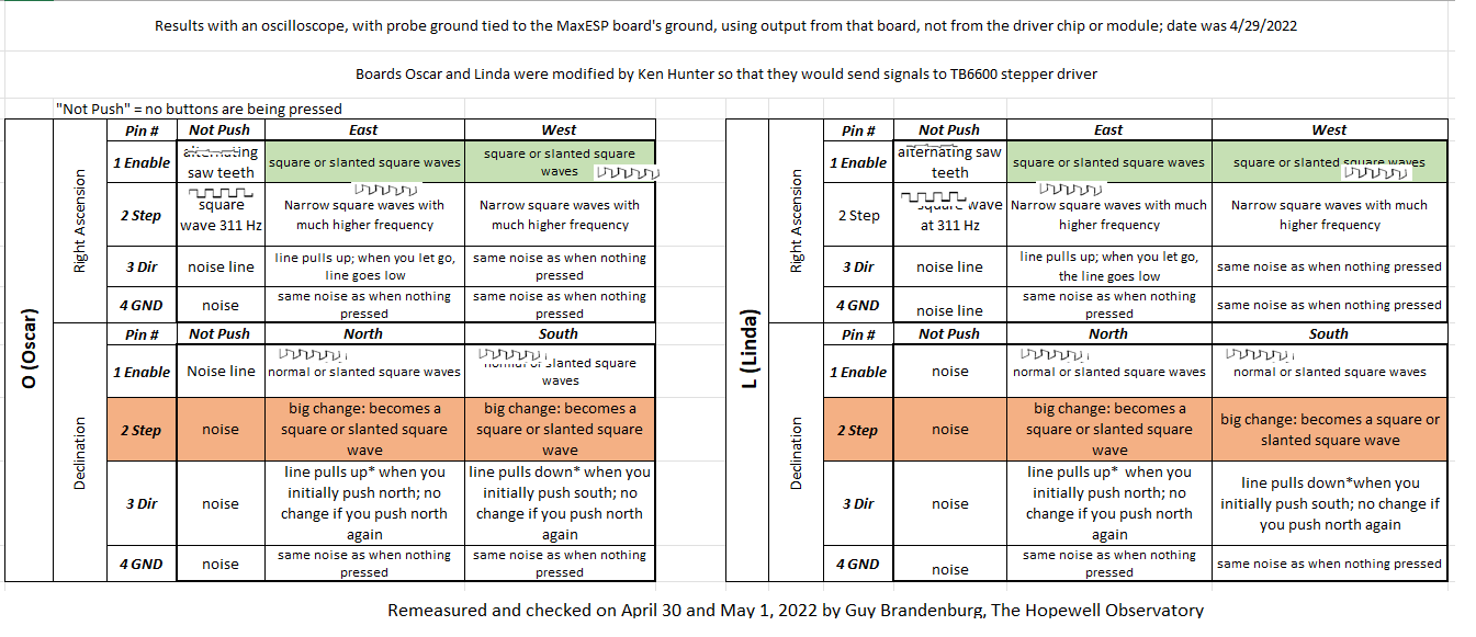
In any case, I attach tables summarizing what I found with the same oscilloscope I had in the previous post. I have highlighted parts that differ between the three boards. Boards “Oscar” and “Linda” are basically identical ones, both of them modified to bypass the location where small, internal stepper motor drivers (about the size of the last joint on your pinky finger) are normally held. Instead, these two boards, both blue in color, connect to two external black-and-green stepper drivers about the size of your hand.
Board “Nancy” differs from the other two in a number of ways: it’s green, which is not important for its function but makes it easier to distinguish. It is also an unmodified one, and it carries TMC5160 stepper driver chips pushed into two rails.

With electronics: when it works, it’s amazing, but it is very, very fragile.
==========================
Edit: It all works just fine on my desk. I hope it will also work once we put it into the telescope’s cavities and wire everything up!
30 Saturday Apr 2022
Posted in astronomy, Hopewell Observatorry, science, Telescope Making, Uncategorized
Tags
Arduino, axes, declination, direction, enable, ground, Hopewell, MaxESP, OnStep, oscilloscope, pin, right ascension, step
We are still at work trying to debug our OnStep re-build of the venerable Ealing telescope drive system at Hopewell Observatory.
Without having a whole lot of experience with oscilloscopes, we used a brand-new OWON 200-series hand-held unit to measure the output of our various MaxESP3.03 boards towards the stepper motors. We don’t really understand what these waveforms actually mean, and a brief search of the OnStep wiki page does not immediately point me to screenshots of what the signals should look like under various conditions.
In any case, some of the waveforms we see look like simple square wave signals. Some look like weird semi-random combinations of square waves, and some look like just plain noise.
In this first video, we have an unmodified MaxESP3.03 board with TMC5160 drivers, not connected to any stepper motors. I attached the ground pin of the probe to one of the grounding grommets at a corner of the MaxESP board, and systematically probed the pins that come out towards the various windings on the stepper motor. We also pressed N, S, E, and W buttons to see what happened. Here goes:
Those of you who are experts on this: do these waveforms appear to be OK to you in this situation?
This next setup is different. It’s a MaxESP3.03 board that Ken Hunter has modified by adding or moving about ten jumpers on the underside of the board; it has no slip-stick drivers for RA or DEC mounted on the MaxESP board itself. Instead, each axis has three (not four) wires coming out of the same place that four wires generally come out to connect to your stepper motor; these three wires connect to four of the inputs on an external, and separately-powered TB6600 stepper driver, which then feeds four wires to the two coils on the stepper.
The arrangement we have now does seem to work, at least on our workbench at the ATM workshop in Chevy Chase Community Center in NW DC, as you can see and hear in this video, but, once again, neither Alan nor I have any idea if the waveforms are correct. Here is the video:
Again: experts — do you think those waveforms are correct?
We were surprised at how complex, and apparently noisy, are the signals on the Step and Dir lines from this modified MaxESP board to the green-and-black external TB6600 drivers. They don’t show up at all in these two previous videos, but they will show up in the next one, which I’m having a bit of trouble uploading at the moment.
In that video, I test both RA and DEC output.
In RA, pin #1 is Enable and is apparently not connected to anything. It produces a wave that looks like a crosscut saw seen from above that has teeth very widely spaced apart. That ENA signal doesn’t change no matter what buttons we push; we think the graph is merely showing interference from something or other.
Still in RA, pin #2 is the STEP pin, and it produces a nice square wave that changes dramatically in frequency when you press the E or W buttons on the SHC. We don’t really see the difference between the E or W graphs.
Still in RA, and in contrast, the graphs for both the Dir and GND pins seem to just look like noise. When one presses ‘E’ the noise graph from the Dir pin definitely changes voltage (it drops off the screen), but not when we press ‘W’. Nothing happens to the noise graph on the fourth pin (GND), no matter what we do.
On the DEC side, all pins seem to put out flat but noisy signals. The noise signal on Pin 2 (Step) moves dramatically but identically lower when you press either the North or South button on the SHC. The noise signal on Pin 3 (Dir) does not change when you press buttons, and neither does the noise signal on pin 4 (GND).
So can we conclude that this board is fried?
16 Saturday Apr 2022
Posted in astronomy, Hopewell Observatorry, Telescope Making
We are still trying to get our venerable, university-grade Ealing mount to work properly with its new OnStep motor drive system. We thought we had – at long last – everything set up perfectly and running correctly with the various components wired up properly but not yet pushed into place in the interior cavities of our mount. All seemed to be working well until we pushed the last components and wires inside, and then closed the hatches.
Then things stopped working.
We soon figured out that the force we had to use when moving all those items inside the mount had broken some of the leads. We found those broken leads and replaced them with shorter ones.
When we started it up again, we discovered that the mount would not ‘track’ to the west in right ascension — something that the software and hardware are programmed to do as soon as the system is turned on. In fact, I couldn’t slew it to the west either. Eastwards was no problem. Also, we could only slew southwards, not northwards.
We didn’t know what to do, so I emailed a followup question to the wonderful folks at the OnStep wiki. Several folks thought we had a balance issue or a limit switch issue, but I went up today to check on the balance — and concluded that’s not the problem. We have no limit switches yet either in hardware or in software. So that’s not it, either.
Wondering if we had somehow screwed up the MaxESP3 board that is the heart of the OnStep system, I unplugged the board (and all of its sub-boards, as a unit) we had been using last weekend, and plugged in a duplicate board, built by Ken Hunter and ‘flashed’ by him with the same Config.H file as the other one.
Listen to the screeching!
Another suggestion is that we may be creating ground loops by not connecting our wiring properly. I don’t know. I wish I had taken some electronics classes during my time in college. It would have come in handy here!
