Tags
astronomy, ATM, filter, Hopewell Observatory, light pollution, Optics, photometry, RR Lyrae, RRLyrae, Seestar, Seestar s50, Telescope
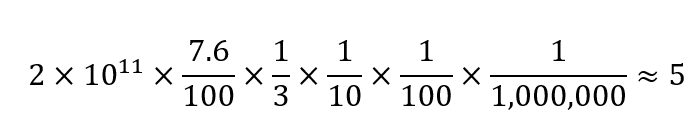
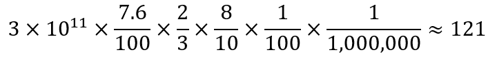
As described in my last post, I got a light curve for a known variable star in my little Seestar S50 a few weeks ago that showed absolutely no variability whatsoever over a roughly 4 hour period. Since this star’s variation occurs extremely regularly, there is a known formula that will give you the precise location in its cycle if you feed in the Julian day (JD). I plugged the start and end times for my run, and got the following:
And was confused

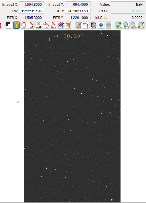
So RRLyrae should have dropped from something near 7.3 magnitude to around 7.6 magnitude, which is a LOT for this sort of thing. But my graph of brightness of RRLyae, compared to a nearby star of roughly the same magnitude, looks like this:

Which is barely any change at all. The few pairs of dots below the blue blob line are glitchy data that should be ignored; notice that it happens for both stars. In fact, I see more variability in the pink comparison star’s brightness than I do with RRRLyrae.
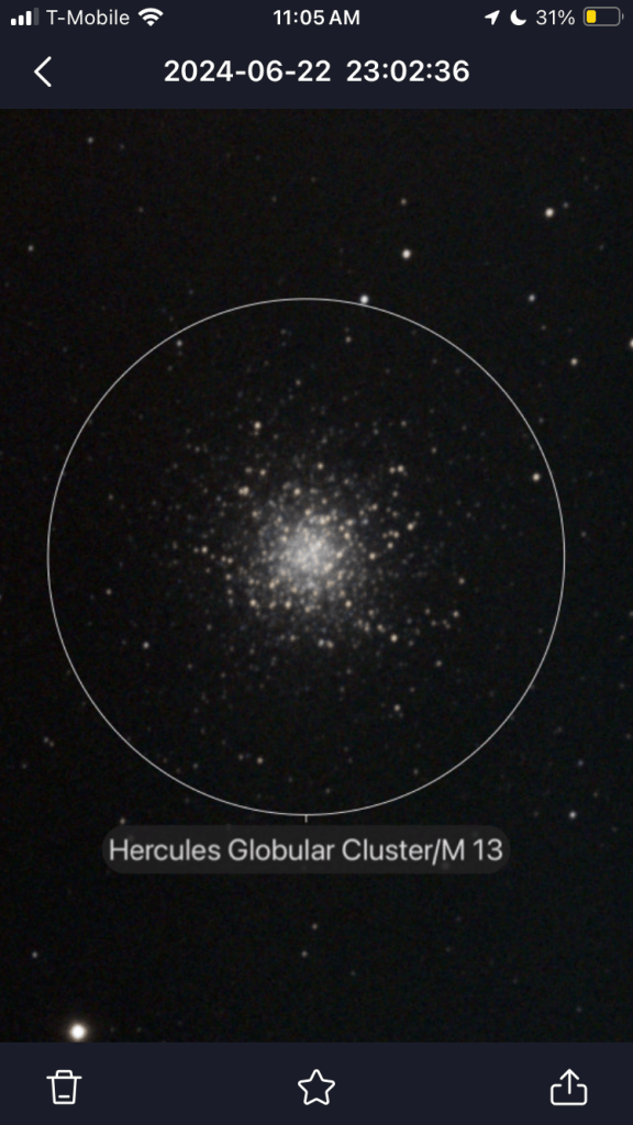
Was the scope indeed pointed at the correct star? Well, I had plate solving on each and every frame, and they all agreed, so, yes.
I did notice a problem with saturation, but didn’t know exactly by how much. Nikolaos Bafitis suggested that I use my mouse to look more closely at the centers of the star images themselves in AstroImageJ. I did so, and at last noticed that one of the boxes held the number of pixel counts right under my mouse pointer. Duh! Sure enough, my target star, RR Lyrae, had a count of 65,533, which is 2^16, and (I looked it up) that is precisely the maximum for these pixels on these CMOS cameras. So that’s why RR Lyrae’s brightness was so steady: it was always OVERFLOWING.
So I have to figure out a way to gather fewer photons per pixel around the target and comparison stars. There are several possible ways of doing so without changing the electronics or trying to mess with the operating system or user interface.
- Reduce the ISO setting from the current default value.
- Shorten the exposure time.
- Change the focal ratio by placing a circular mask over the lens aperture.
- De-focus the images so that the light is spread out over a larger area.
- Add some sort of filter.
Unfortunately right now, the Seestar doesn’t allow you to do either number 1 or number 2. It would be nice if ZWO engineers would add those capabilities in the ‘advanced’ menu,
Number 3 is quite doable. I happen to have on hand a large roll of black Kydex plastic and a set of Forstner bits to make nice holes with. But it this would require a fair amount of time and effort. It would also reduce the resolution of an already rather small 50mm lens.
Number 4 is more easily doable: turn off the autofocus feature and do some experimentation to find a good fixed de-focus point. However, if the stars are too fuzzy, then plate-solving becomes much harder and slower.
Number 5 can be done by using the built-in light pollution filter, whose transmission bandwidth is very small. It’s the bottom graphic below.
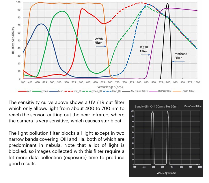
The graphics above come from an excellent Unofficial Seestar handbook written by Tom Harnish. He has a number of suggestions that I hope the engineers at ZWO pay attention to and follow.
The option that seems easiest is number 5, using the light pollution filter. If I couple that with the built-in time-lapse feature, I won’t fill the Seestar’s entire memory with a zillion FITS images.
I hope to try this tonight up at Hopewell Observatory, where I can set this up, have it run all night connected to mains power, and I can sleep in a nice warm cabin.
And maybe get lucky and see Northern Lights!