• My series on making a Newtonian telescope
  • How Leon Foucault Made Telescopes

Guy's Math & Astro Blog

Guy's Math & Astro Blog

Tag Archives: ATM

First Time Installation of OnStep Board with NEMA23 Stepper Motors in Ealing Mount at Hopewell

03 Monday Jan 2022

Posted by gfbrandenburg in astronomy, Hopewell Observatorry, Optics, science, Telescope Making

≈ 2 Comments

Tags

ATM, Bob Bolster, dobsonian, Hopewell Observatory, Howard Dutton, OnStep, OnStep Conversion, Telescope

A 3-minute video of the results of our first-time installation of something called an OnStep conversion. We are replacing the telescope drive of a venerable but beautifully machined telescope mount, located at a small group-owned observatory called Hopewell, atop a ridge called Bull Run Mountain*.

It’s alive!

Sorry, it’s not the greatest or clearest video. Also, I mistakenly state at about 0:25 in the video that the right ascension axis was turning at 12 RPM, but it’s not: I should have said 5 RPM, or one revolution in 12 seconds.

You can hear some stuttering of one of the motors. You are right, that is not a good sound. We were able to get it to stop and start making that noise and motion by adjusting the precise positioning of some of the gears. It will take some time and experimentation to get that perfect.

Later on (not captured in this video), when I was trying to slew in the declination axis at the highest speed possible, the stepper motor once again screamed and halted. I’m hopeful that all of those problems can be fixed by doing one or more of these things:

  • 1) adjusting the fit of all those gears;
  • (2) changing certain parameters of microstepping and current to the stepper motors in software; and/or
  • (3) increasing the voltage to the board from 18 VDC to 24 VDC.

I’ll need to test things out on my desk at home, using the same OnStep board, but without the gears and timing belt. (That stuff was a royal PITA to remove screw back into place, and none of us have any desire to take them back out again!) I have some identical extra stepper motors that I can test out, with gloved hands, to see if it is possible to stop the motors from turning. Right now, I still don’t think they are putting out the amount of torque needed.

================================

*Yes, that famous Bull Run of Civil War fame is not far away. However, our observatory is named after a different geological feature, namely the Hopewell Gap that cuts through the hard rock of Bull Run Mountain right about where where the creek called Little Bull Run begins.

If you are reading this, you probably know that serious amateur, and all professional, astronomical telescopes (except for Dobs) are generally driven by ‘clock drives’ so that the object one is viewing or photographing stays properly centered as the earth rotates imperceptibly beneath us. The original Ealing motor drive at Hopewell, while turning excellent Ed Byers gears, had been an intermittent problem ever since it was delivered to the University of Maryland about 50 years ago. It was in fact not operational when they sold it to us for a pittance about 30 years ago. (If you go to the University of Maryland Observatory site I linked to, the scope we have now is the one in the center of the 1970s – era photo labeled ‘Figure 4’.)

Bob Bolster, one of the founding members of Hopewell observatory, disassembled the drive, modified it considerably, and got it working again, several years before I joined the group. The scope worked, off and on, with a very complex clutch system for ‘fast’ and ‘slow’ movement of the scope, for most of the rest of the last 25 or so years, except for occasional motor burnouts and clutch replacements. Also unfortunately, the optics on the original 12″ Ritchey-Chretien telescope, were not very good, so we removed them, had them in an attic for many years, re-tested them, and finally sold the glass and the holders, for a pittance, to someone in Italy who wanted to try to re-figure them.

This was originally a ‘push-to’ telescope, meaning that one loosened up two Byers clutches (one for each axis), located the desired target in the sky, tightened the two clutches, did some fine tuning with an electric hand paddle to center the target more precisely, and then allowed the telescope drive to then keep the object in the center of the eyepiece or camera field of view as long as one wanted. It originally came with metal setting circles (basically, finely-made protractors that showed where the scope is pointing vis-a-vis the polar and declination axes), which made finding targets possible, though not trivial!

About 15 years ago, Bolster (with some help from me) installed Digital Setting Circles, which used a rotary encoder on each axis, along with a small hand-held computer and screen display, to allow one to select a given target; the DSC hand paddle’s display then would indicate how far one should rotate the scope along those axes to find the desired celestial object; when it was in the field of your widest eyepiece, one used the hand paddle to center it more precisely.

Converting this scope to an OnStep drive will, I hope, make this a Go-To scope in which one can command the telescope to aim at whatever target one desires.

Unfortunately, right now, the fastest it seems to rotate in Declination, with no load whatsoever (all scopes have been removed, so no balance or inertia problems) is about one degree per second. So doing a 180-degree turn in a North-South direction would take a full three minutes. A 30-degree turn would take 30 seconds. Can we make this a bit faster? I hope so.

I wasn’t able to really slew in right ascension (East-West) because the counterweight box, even though empty, seems to require too much torque to rotate right now.

Bolster passed away a few years ago, and this summer, the moment I had been dreading finally arrived: the drive on the Ealing died again, and his amazing skills and tenacity in fixing such problems was gone with him. What’s more, in his final years, his incurable, chronic idiopathic neuropathy made it literally impossible for him to speak, and even typing email responses to the rest of us took a very long time. So most of his wealth of knowledge and experience died with him.

As indicated in my earlier posts (here, here, here, and here), with help from others, I was able to take the two motor setups for the two axes out from the mount and get them working again on my workbench in their original format. I was even able to order and install material for the clutches. However, I discovered that one needed to adjust the clutches very, very precisely, or else they wouldn’t work at all.

I couldn’t figure out how to do that.

And nobody else who belongs to our observatory volunteered to help out, except for removing the scopes and drives from their former positions inside the mount.

So I decided to convert to a totally different type of telescope drive, one inspired by the Arduino boards and 3-D printers. A group of really smart and resourceful hobbyists (engineers?) designed a system around the Arduino environment that uses inexpensive off-the-shelf printed circuits and complex sub-boards and components, used originally mostly in the 3-D printers that have become so popular, to drive at telescope just the way astronomers want them to be driven.

Apparently, there have been many, many OnStep successes, but what we are doing may be the largest and most massive mount to date that has done such a conversion.

I was warned that the entire process would take some months. Those warnings were correct. But that’s OK. I’m retired, I have time, and I have access to tools and people who are interested in helping. What’s more, I have learned a whole lot about modern electronics, and my soldering skills are much better than they ever were.

I’d again like to thank Alan Tarica (who’s physically helped a **tremendous** amount), Prasad Agrahar (who first showed me the OnStep conversions he had done on a much smaller equatorial mount), Howard Dutton (who first conceived and implemented OnStep), Ken Hunter (who made and **donated** to us a complete, functional OnStep board together with all sorts of accessories and walked me by phone and video through many of my fumbling first steps), Khalid Bahayeldin, George Cushing, and many others.
Progress and Problems with an OnStep Conversion of a High-Quality 1970’s Telescope Drive

31 Friday Dec 2021

Posted by gfbrandenburg in astronomy, Hopewell Observatorry, Optics, Telescope Making, Uncategorized

≈ 2 Comments

Tags

Arduino, Astrophotography, ATM, Hopewell Observatory, OnStep, Stepper Motors, Telescope

I have made a lot of progress over this winter break in converting the 50-year-old Ealing telescope mount at the Hopewell Observatory, as you can see in this video.

We are swapping out an electro-mechanical “dumb” drive that failed, in favor of a modern, solid-state one built in the Arduino environment. If it all works out as planned, this mount will be able to slew to any target and keep the target steady enough for astrophotograpy. I hope.

With a project like this, with delicate electronics that can easily get fried, I believe that having spare parts on hand is a good idea. The main board is pretty cheap: under $100, completely assembled, and the motors were about $30 each. We have spare stepper motors, spare stepper drivers, and a total of three main MaxESP OnStep boards.

Except that two of them (the ones we purchased from George C) don’t work at all, and I don’t know why. The one that Ken Hunter built and **donated** to us works just fine, after I did the required tweaking of various settings inside the Smart Hand Controller or SHC and inside a CONFIG.H file in the Arduino programming environment. And added the gears and belt.

I see almost no serious differences between George’s boards and Ken’s board. I am confident the problem is not my wiring or soldering, and it’s not the fact that George’s boards have RJ45 jacks, but what it is, I have no idea.

This is my second build of the connections between the stepper motor and the worm gear.

Without the help of Ken H, Howard Dutton, another Ken, Alan Tarica, Prasad Agrahar, and Khaled Bahayeldin, I never would have gotten this far. I am very appreciative of the amount of work that went into programming all of the many parts of the OnStep project as a whole. However, I found the OnStep Wiki rather confusing for beginners, and I hope to help them make it clearer in the future.

You can probably see that there is a good bit of wobble in the gears that involve the belts. That is probably because I failed to get the gears perfectly flush against the lathe chuck when I was enlarging their central holes from 5 mm to 1/4 inch despite using a dial indicator with a magnetic base to center it. I think I will need to order a new set of gears that have a 1/4″ axle hole already made at the factory. I don’t think I can do any better than I did, and that wasn’t good enough.

The reason for having the gears and belts is something to do with microstepping on the stepper motors that I really don’t understand. OnStep experts told me that the OnStep board, drivers, and steppers simply cannot handle gears that are 1 : 20 : 359. So we added a 3:1 toothed-gear-and-belt system so that the ratios are now 3 : 1 : 20 : 359. That set of ratios seems to make the steppers happy. (These motors have 200 steps per rotation, and are being currently driven at a rate of 1/16 of a step.) They don’t scream and stall any more, but the wobbly gears will probably translate into periodic error that one can see in the eyepiece or on long exposures with some kind of camera.

My next step is to take this entire apparatus up to the Hopewell Observatory itself and see what happens when I install them in the Right Ascension and Declination drives.

Then, we need to repair the electrical supply for the roll-off roof.

Then we have to put the telescopes back onto the mount.

Then, and only then, can we try having a “First Light” with the new motor pushing a very nice Ed Byers drive in an big, old, and very well-built university-grade telescope mount.

A piece of mystery glass

29 Sunday Aug 2021

Posted by gfbrandenburg in astronomy, Hopewell Observatorry, Math, Optics, Telescope Making

≈ 3 Comments

Tags

ATM, barium, Bausch & Lomb, Bureau of Standards, flint, glass, Hopewell Observatory, Math, mystery glass, Optics, Schott, Snell's Law, Telescope

Many years ago, the late Bob Bolster, a founding member of Hopewell Observatory and an amazing amateur telescope maker, got hold of a large piece of glass, perhaps World War Two military surplus left over from the old Bureau of Standards.

I have no idea what it is made out of. If Bob had any clue about its composition, he didn’t tell anyone.

Its diameter is 22 inches, and its thickness is about 3.25″. It has a yellowish tint, and it is very, very heavy.

If you didn’t know, telescope lenses (just like binocular or camera lenses) are made from a wide variety of ingredients, carefully selected to refract the various colors of light just so. Almost all glass contains quartz (SiO2), but they can also contain limestone (CaCO3), Boric oxide (B2O3), phosphates, fluorides, lead oxide, and even rare earth elements like lanthanum or thorium. This link will tell you more than you need to know.

If you are making lenses for a large refracting telescope, you need to have two very different types of glass, and you need to know their indices of refraction very precisely, so that you can calculate the the exact curvatures needed so that the color distortions produced by one lens will be mostly canceled out by the other piece(s) of glass. This is not simple! The largest working refractor today is the Yerkes, with a diameter of 40 inches (~1 meter). By comparison, the largest reflecting telescope made with a single piece of glass today is the Subaru on Mauna Kea, with a diameter of 8.2 meters (323 inches).

For a reflecting telescope, one generally doesn’t care very much what the exact composition of the glass might be, as long as it doesn’t expand and contract too much when the temperature rises or falls.

We weren’t quite sure what to do with this heavy disk, but we figured that before either grinding it into a mirror or selling it, we should try to figure out what type of glass it might be.

Several companies that produce optical glass publish catalogs that list all sorts of data, including density and indices of refraction and dispersion.

Some of us Hopewell members used a bathroom scale and tape measures to measure the density. We found that it weighed about 130 pounds. The diameter is 22 inches (55.9 cm) and the thickness is 3 and a quarter inches (8.26 cm). Using the formula for a cylinder, namely V = pi*r2*h, the volume is about 1235 cubic inches or 20,722 cubic centimeters. Using a bathroom scale, we got its weight to be about 130 lbs, or 59 kg (both +/- 1 or 2). It is possible that the scale got confused, since it expects two feet to be placed on it, rather than one large disk of glass.

However, if our measurements are correct, its density is about 2.91 grams per cc, or 1.68 ounces per cubic inches. (We figured that the density might be as low as 2.80 or as high as 3.00 if the scale was a bit off.)

It turns out that there are lots of different types of glass in that range.

Looking through the Schott catalog I saw the following types of glass with densities in that range, but I may have missed a few.

2.86  N-SF5

2.86 M-BAK2

2.89 N-BAF4

2.90 N-SF8

2.90 P-SF8

2.91 N-PSK3

2.92 N-SF15

2.93 P-SF69

2.94 LLF1

2.97 P-SK58A

3.00 N-KZFS5

3.01 P-SK57Q1

By comparison, some of the commonest and cheapest optical glasses are BAK-4 with density 3.05 and BK-7 with density 2.5.

Someone suggested that the glass might contain radioactive thorium. I don’t have a working Geiger counter, but used an iPhone app called GammaPix and it reported no gamma-ray radioactivity at all, and I also found that none of the glasses listed above (as manufactured today by Schott) contain any Uranium, Thorium or Lanthanum (which is used to replace thorium).

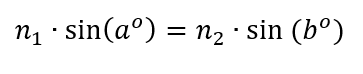
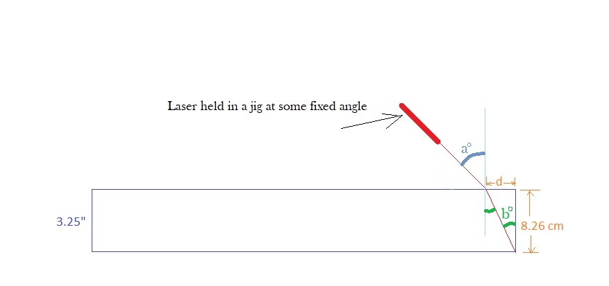
So I then rigged up a fixed laser pointer to measure its index of refraction using Snell’s Law, which says

Here is a schematic of my setup:


The fixed angle a I found to be between 50 and 51 degrees by putting my rig on a large mirror and measuring the angle of reflection with a carpentry tool.

And here is what it looked like in practice:

I slid the jig back and forth until I could make it so that the refracted laser beam just barely hit the bottom edge of the glass blank.

I marked where the laser is impinging upon the glass, and I measured the distance d from that spot to the top edge of the glass.

I divided d by the thickness of the glass, in the same units, and found the arc-tangent of that ratio; that is the measure, b, of the angle of refraction.

One generally uses 1.00 for the index of refraction of air (n1). I am calling n2 the index of refraction of the glass. I had never actually done this experiment before; I had only read about doing it.

As you might expect, with such a crude setup, I got a range of answers for the thickness of the glass, and for the distance d. Even angle a was uncertain: somewhere around 49 or 50 degrees. For the angle of refraction, I got answers somewhere between 25.7 and 26.5 degrees.

All of this gave me an index of refraction for this class as being between 1.723 and 1.760.

This gave me a list of quite a few different glasses in several catalogs (two from Schott and one from Bausch & Lomb).

Unfortunately, there is no glass with a density between 2.80 and 3.00 g/cc that has an index of refraction in that range.

None.

So, either we have a disk of unobtanium, or else we did some measurements incorrectly.

I’m guessing it’s not unobtanium.

I’m also guessing the error is probably in our weighing procedure. The bathroom scale we used is not very accurate and probably got confused because the glass doesn’t have two feet.

A suggestion was made that this might be what Bausch and Lomb called Barium Flint, but that has an index of refraction that’s too low, only 1.605.

Mystery is still unsolved.

Australian TV Bit on Me and the DC ATM Workshop

27 Monday Nov 2017

Posted by gfbrandenburg in astronomy, astrophysics, nature, Safety, science, Telescope Making

≈ Leave a comment

Tags

2017, ATM, Australia, eclipse, Stephanie March, Telescope

Some very nice folks from the Australian Broadcasting Corporation came and interviewed me on film for a bit on folks who make their own telescopes to see the great August 2017 eclipse. Here is the link:

( https://www.facebook.com/abcnews.au/videos/10157157152414988/ )

Another recent scope at the NCA – ATM workshop at the CCCC

11 Friday Mar 2016

Posted by gfbrandenburg in astronomy, Telescope Making

≈ Leave a comment

Tags

ATM, CCCC, NCA

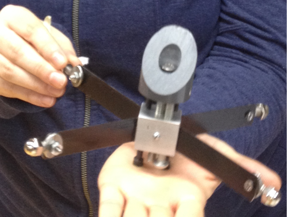
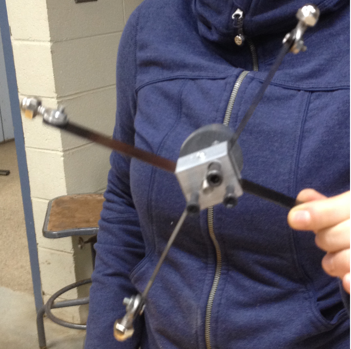
This ultra-short scope, by Todd M, has a mirror of 4.25″ (108 mm) and a pretty short focal length – about 2 feet (60 cm). He made just about everything, right here in the NCA ATM workshop at the Chevy Chase Community Center. He ground, polished, figured, and even helped aluminize the primary mirror; made the primary cell AND the spider and secondary holder; made all of the rest of the mount that you see; and even made the focuser itself from some plumbing parts!

IMG_4104
IMG_4106

It’s a very nice job, meriting a lot of praise. In case you were wondering, the paint was a special, very-high quality and very expensive top-of-the-line alkyd enamel, costing about $200 per gallon – and we have two of them. Explanation: it was an ‘oops’ can that was specially ordered and mixed for someone who changed their mind and couldn’t return it. In exchange for a non-profit donation receipt in the name of NCA, Bill R was able to get the person to donate both gallons to us.

The spider and secondary holder are very similar to the one made by Ramona D that you can see here. The major differences are:

(1) Todd used busted bandsaw blades rather than steel strapping tape for the vanes. (Both were the same price: free.) After looking at both projects, which both turned out quite nicely, my conclusion is that if you want to use bandsaw blades, you have to heat-treat (anneal) them so they will have less of a tendency to break right at the location where you are trying to bend them by 45 degrees. (Heat it up to cherry red and then let it cool slowly in the air, making it softer and less brittle, I am told…)

(2) And of course, it certainly helps to grind down the teeth of the bandsaw blade both for safety and to reduce weird reflections. Strapping tape is about the same thickness as many band saw blades, but the tape is wider and hence more stable and less prone to turn crooked (I think).

(3) Todd used ordinary 1/4″-20 machine screws (aka bolts) to attach the vanes of the spider to and through the walls of the tube. He cut off the heads of the bolts and ground one side flat near the head, and then drilled a little hole in that flat part, tapped (threaded) that, and used a tiny little machine screw to attach the vane to the specially-prepared screw, in a process that I hope is clearly shown in these three drawings.

Begin with a machine screw (bolt)
Cut off the head, use a grinder or saw to make a flat area (or else you can split the screw down the middle)
Drill and tap (i.e., thread) the little hole; attach to vane; feed the far end through a hole in the wall of the tube; attach securely with a washer and nut.

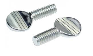
(4) Ramona, however, used thumbscrews instead of doing all that cutting, filing and tapping. Actually, our little tiny tapping drills didn’t play well with our bit holders – they kept slipping. So she just drilled holes in the center of each thumbscrew head, and bought three very small nuts and bolts and used them in the place of the little screw that Todd used.

(Thumbscrews like these:)

thumbscrews

One Way to Make a Telescope Spider

05 Saturday Mar 2016

Posted by gfbrandenburg in astronomy, Telescope Making

≈ 4 Comments

Tags

ATM, diagonal, dobsonian, spider, Telescope

All Newtonian telescopes require a secondary mirror — a flat mirror held at roughly a 45-degree angle to reflect the light from the primary out to the side. Generally this secondary mirror is an ellipsoid, in order to waste as little light as possible.

One major problem is figuring out how to hold this secondary mirror in place securely without interfering with the passage of light from your distant target. The secondary mirror can be held on a stalk, or on crossed arms like a spider’s web.

The images below show how Ramona D made a spider using a piece of extruded aluminum tube with a square cross section, several bolts, a spring, a piece of plastic dowel, some pieces of steel strapping tape, a few thumbscrews, and various small nuts and bolts. She did a very neat job, including threading and tapping several small holes in the aluminum tube.

The idea is not original to me: I got the idea from somebody else on line, but unfortunately, I don’t recall the name of the person to whom I should give credit.

Here are some photos that probably do a better job of explaining how to make it than I could explain in many, many paragraphs.

ramonas spider 1.png

ramonas spider 2

ramonas spider 3

ramonas spider 4

Telescope Making in Cuba?

04 Friday Dec 2015

Posted by gfbrandenburg in Telescope Making

≈ Leave a comment

Tags

ATM, cuba, dobsonian, Grit, Mirror, Optics, Polishing, Telescope

Inspired by a Canadian amateur astronomer who visited the place, I’ve been in recent contact by email with some potential amateur telescope makers in Cuba. 
 .
I proposed bringing the optics for some completed 4″ to 8″ Newtonian telescopes in my luggage (ie parabolized & aluminized mirrors, diagonals, and eyepieces) and then giving them ideas and assistance on making the rest of the scopes. I have a number of already-completed primaries and diagonals at our DC telescope making workshop, but would have to scrounge around for eyepieces. 
 .
(If mechanics in Cuba can keep 1958-model cars running for over 50 years, I bet that they can probably improvise other stuff a la John Dobson, if they have any raw materials at all, which I am not sure about). I am also not sure whether I should bring focusers and spiders, or whether they should make them there themselves…
 .
I understand from the Cubans that there are almost no telescopes in the entire country except for one no-longer-operational telescope at the University of Havana’s observatory, and certainly no Dobsonians. They sound quite interested in the idea, and also were suggesting that I might stay long enough to demonstrate how to grind and polish and figure a mirror.  If I follow up on that idea, it would probably require me bringing in abrasives and pitch in addition to the finished mirrors, which might cause further luggage problems. Explaining finished mirrors carefully wrapped up is one thing, but containers of, say, 15-micron WAO microgrit? They might cut open the bag and test to see if it’s really cocaine…. thus contaminating it…
 .
Both the Canadian and the Cubans said that bringing in materials officially labeled as ‘gifts’ would entail lots of red tape and delays.
.
For me, the payback would be the chance to practice my crappy Spanish in an exotic place that I’ve never visited, and to observe from Tropical skies that suffer relatively low light pollution, as well as doing some good in a country that seems to have a low violent crime rate…. I was planning on flying to Mexico or the Bahamas and then getting a flight to Havana, which seems cheaper than an official direct flight. I suspect that since this would be a scientific exchange, I might even be able to get both governments to sign off and issue an official visa or whatever.
 .
Any thoughts? Anybody ever been there?

Puzzlement when Trying to Figure a Convex Surface Through the Back

14 Saturday Nov 2015

Posted by gfbrandenburg in astronomy, flat, optical flat, Telescope Making

≈ Leave a comment

Tags

ATM, convex, figuring, polarizing filters, Ronchi, strain

Have you ever tried to make a convex optical surface?

If so, you know that it’s much more challenging than a concave one, since the rays of light do not come to a focus at all.

Some of us* at the Amateur Telescope Making workshop here in Washington DC have made several attempts at doing this, pretty much without success. I would like to show you some weird images that we got when we tried to ‘figure’ the convex surface by performing a Ronchi test from the back side, looking through what was supposed to be a flat.

What we find is that even though the glass itself is very clear and free of visible strain when seen by the naked eye or when using crossed polarized filters, it looks like we are looking through an extremely murky and totally un-annealed piece of ancient Venetian glass, causing all sorts of weird striations in what should otherwise be nice, smooth Ronchi lines.

These pictures go in order from outside the radius of curvature to inside the ROC.

IMG_3656 IMG_3660 IMG_3663 IMG_3665 IMG_3667 IMG_3668

You might well think that the glass itself has lots of strain left in it, causing the very weird patterns that you see here. I can prove that this is not the case by showing you a short video that we made with crossed polarizing filters of the 5-inch diameter blank itself and two pieces of plastic (the protective covers for one of the filters). Judge for yourself.

This is not the first time that this strange phenomenon has occurred.

Any suggestions from those with actual experience would be extremely welcome.

===================

* Me, Nagesh K, and Oscar O.

Great Long Weekend of Observing Near Spruce Knob, WVa at 11th Almost Heaven Star Party

18 Tuesday Aug 2015

Posted by gfbrandenburg in astronomy, Telescope Making

≈ Leave a comment

Tags

AHSP, astronomy, ATM, dobsonian, star party

I put all of my tickets (over 30!) into the raffle for a 100-degree-apparent-field-of-view eyepiece at AHSP but didn’t win it. I probably should have put a few tickets in some other raffles. They had a whole lot of different stuff being raffled off. The eyepiece I wanted was donated by Hands On Optics. At AHSP they give you ten tickets as part of your registration, and then you can buy more of them. Elizabeth Warner and her husband left the morning of the raffle (Sunday) and gave me theirs, which was very nice of them.

At Stellafane, they used to have just ONE humongous item in the raffle, like a full set of really expensive eyepieces from Al Nagler. So it used to be in fact all-or-nothing. Don’t know if it was like that this year?
I discovered that the things I really needed were:
* an inexpensive laser collimator so I can get collimated in a minute or two all by myself, accurately, instead of fumbling around for an hour and needing an assistant… (now on order)
* an inexpensive electronic timer controller for my Canon TSi so it doesn’t need any cables to a computer (also now on order)
* a way to get rid of dew. The last night was fantastic except for the dew, which even defeated the chemical hand warmer packets that I wrapped around my finder and Telrad. I bet it got to the secondary as well. I will study up on the physics of heat production by resistors or heating wire wrapped around those and devise something.
BTW, I had to use a borrowed hack saw and masking tape to cut each of my truss tubes by exactly an inch on the second day so that I could come to a focus with all my eyepieces. I used some local rocks to deburr the cuts.
They had some great presentations on astrophotography, including how to do it simply and effectively. I was much encouraged.

Adventures in Making a Glass Surface Optically Flat

13 Friday Feb 2015

Posted by gfbrandenburg in flat, monochromatic, optical flat, Telescope Making

≈ Leave a comment

Tags

ATM, CCCC, flat, interference testing, mercury vapor, monochromatic, optical flat

I’ve been trying to make an optical flat for some time now. It’s not easy, even if you are starting with a piece of ‘float’ glass – modern 3/4″ thick window sheet glass that is manufactured by floating a layer of molten glass on a bath of molten tin.

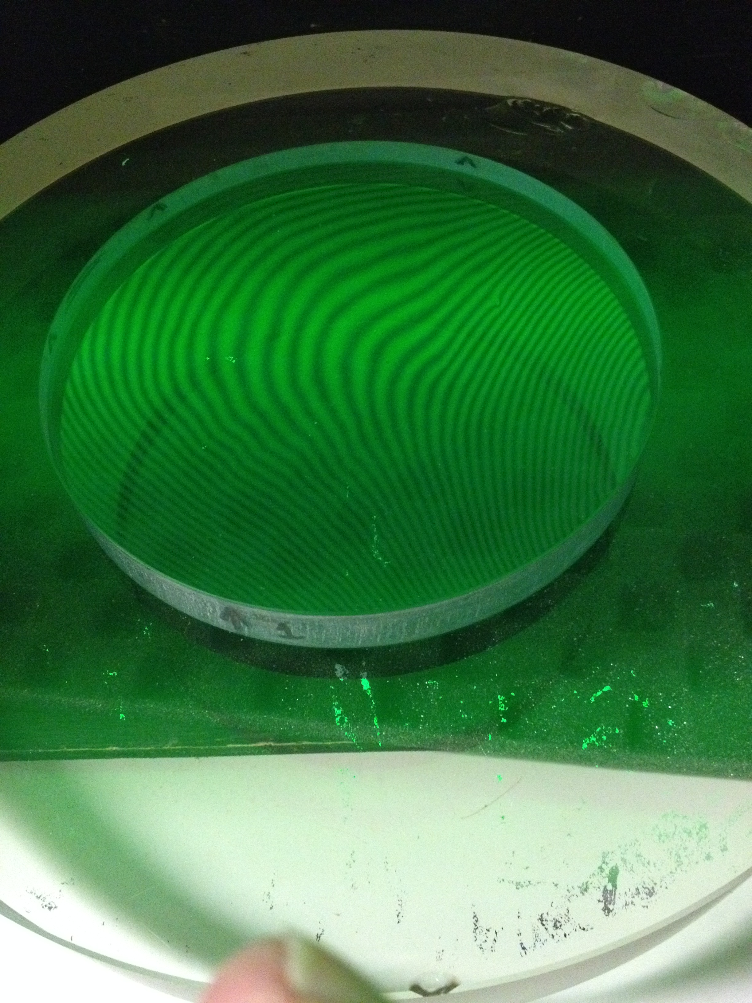
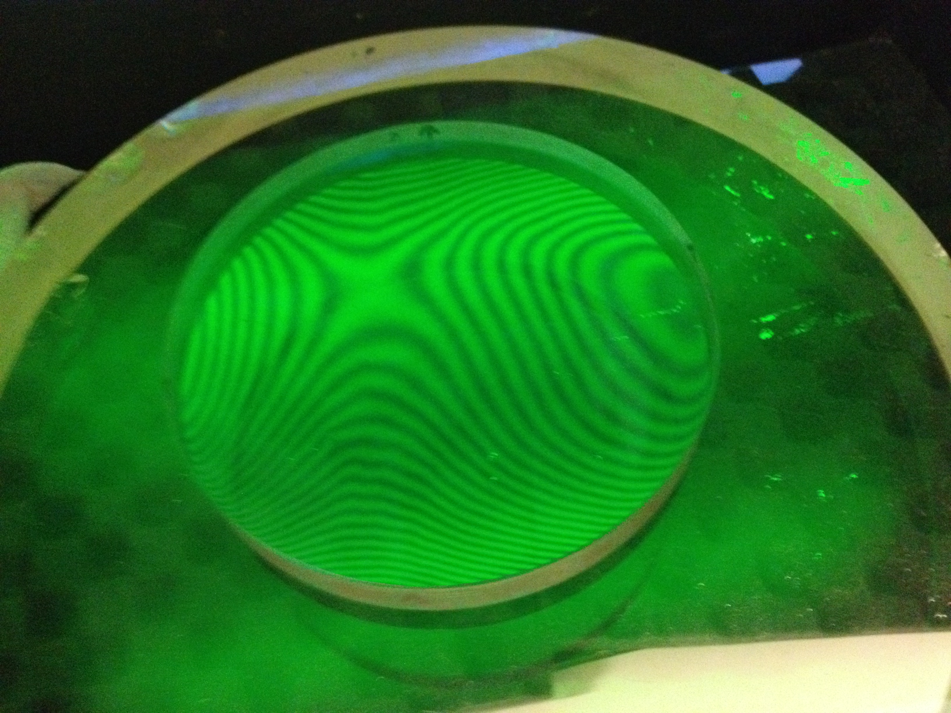
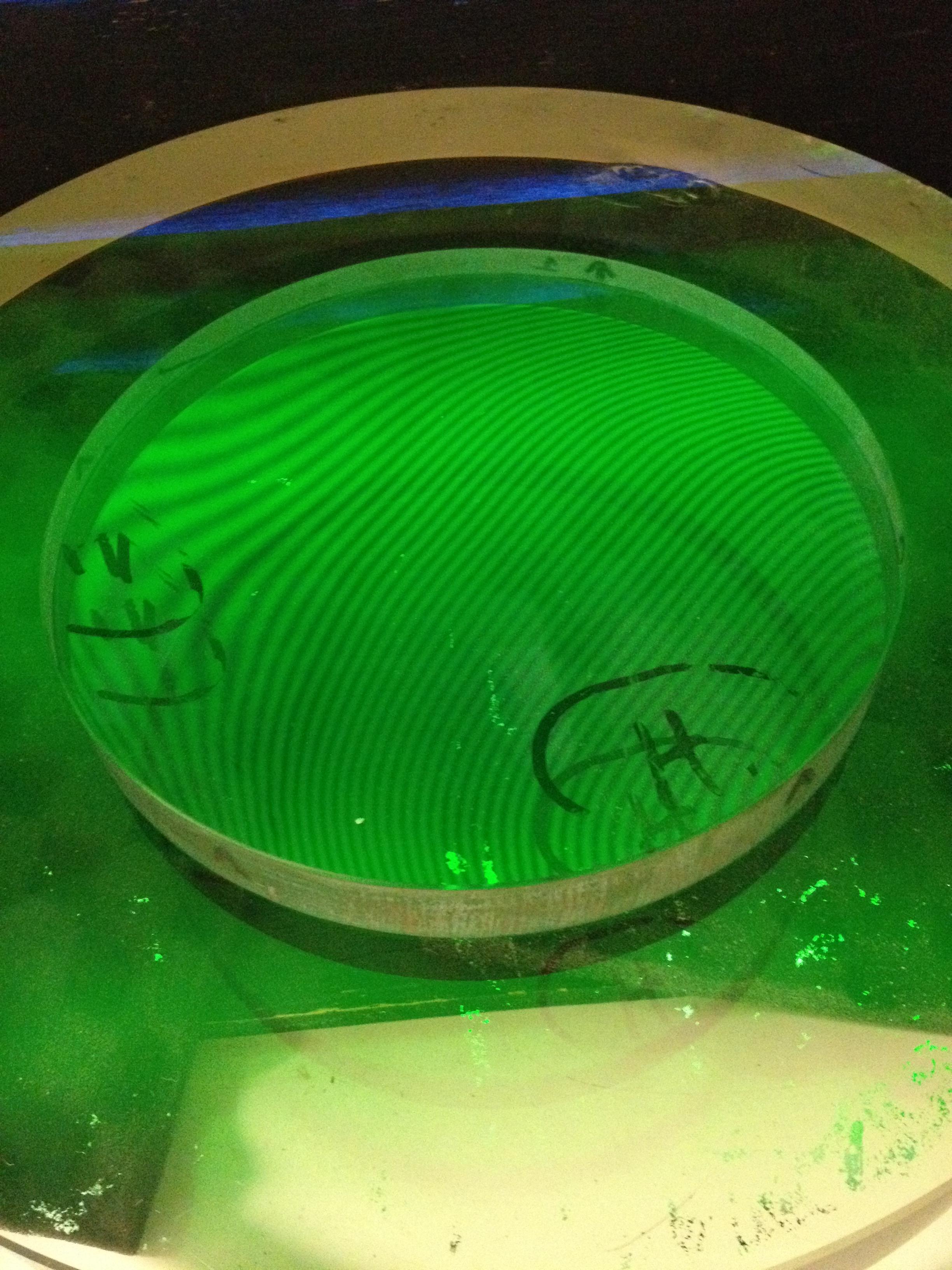
The test apparatus consists of a supposedly-flat 12-inch diameter and a monochromatic light box, and my own gradually-increasing understanding of what the interference lines actually mean. Essentially, they are like contour lines on a topographic map, but the trick is to figure out which sections represent valleys and which ones represent hills. It’s taken help from other amateur telescope makers (particularly Philip P) and sections of Malacara’s book on Optical Testing and http://www.lapping.com .

It’s pretty amazing how we can measure stuff that is soooooo small!

Here are some photos in chronological order of my working on them. I would paste some videos but WordPress won’t allow them and I don’t feel like uploading them to YouTube. BTW: I am not done!!!

022

006

008

009

That’s me looking skeptically at my cell phone, pretending to look skeptically at the glass.010

001

Up until this point I was trying to make the flat more perfect by using a hard Gugolz lap of full size (6 inches in diameter), much as we do with parabolizing concave mirrors. I don’t think I made a whole lot of progress. Then I read some of the papers that Philip P sent me, and re-read the Malacara, and decided to think of the contour lines in terms of measures of height, and decided to use a two-inch-diameter lap only on the parts that appeared to be “high”. I marked the back of those regions with a Sharpie permanent marker (which comes off easily with isopropyl alcohol when needed) so I could see where to work and could see if what I did made any difference.flats i guess 001The places that I marked with the letter H were High spots, kind of like you see on a weather map that is plotting isobars (lines connecting places with the same barometric pressure). The lower right-hand corner was one of those places, as was the smudged region at about 9 o’clock.

BTW I got the green color by using ordinary fluorescent lamps and two carefully-selected theatrical lighting gels to filter out all the light with wavelengths either longer than or shorter than the green Mercury vapor line of 5461 Angstroms.

By the way: I’ve discovered that the 12-inch-diameter optical flat that is underneath my 6 inch test flat isn’t as flat as I thought. Boo.

Will work on this some more this afternoon.

← Older posts
Newer posts →

Subscribe

  • Entries (RSS)
  • Comments (RSS)

Archives

  • August 2026
  • July 2026
  • June 2026
  • May 2026
  • April 2026
  • February 2026
  • December 2025
  • November 2025
  • October 2025
  • September 2025
  • July 2025
  • January 2025
  • November 2024
  • October 2024
  • August 2024
  • July 2024
  • May 2024
  • April 2024
  • January 2024
  • December 2023
  • October 2023
  • August 2023
  • June 2023
  • May 2023
  • April 2023
  • November 2022
  • October 2022
  • August 2022
  • July 2022
  • June 2022
  • May 2022
  • April 2022
  • February 2022
  • January 2022
  • December 2021
  • October 2021
  • September 2021
  • August 2021
  • July 2021
  • June 2021
  • May 2021
  • March 2021
  • December 2020
  • October 2020
  • September 2020
  • August 2020
  • March 2020
  • February 2020
  • January 2020
  • December 2019
  • November 2019
  • September 2019
  • August 2019
  • June 2019
  • May 2019
  • January 2019
  • November 2018
  • October 2018
  • September 2018
  • August 2018
  • May 2018
  • March 2018
  • January 2018
  • November 2017
  • October 2017
  • September 2017
  • August 2017
  • July 2017
  • June 2017
  • May 2017
  • April 2017
  • February 2017
  • December 2016
  • September 2016
  • June 2016
  • May 2016
  • April 2016
  • March 2016
  • February 2016
  • January 2016
  • December 2015
  • November 2015
  • August 2015
  • July 2015
  • April 2015
  • March 2015
  • February 2015
  • January 2015
  • December 2014

Categories

  • astronomy
  • astrophysics
  • education
  • flat
  • History
  • Hopewell Observatorry
  • Math
  • monochromatic
  • nature
  • optical flat
  • Optics
  • Safety
  • science
  • teaching
  • Telescope Making
  • Uncategorized

Meta

  • Create account
  • Log in

Blog at WordPress.com.

  • Subscribe Subscribed
    • Guy's Math & Astro Blog
    • Join 54 other subscribers
    • Already have a WordPress.com account? Log in now.
    • Guy's Math & Astro Blog
    • Subscribe Subscribed
    • Sign up
    • Log in
    • Report this content
    • View site in Reader
    • Manage subscriptions
    • Collapse this bar
Loading Comments...