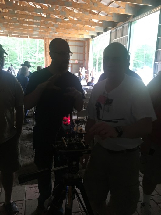
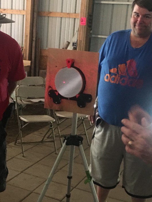
I am posting some photos and videos of the demonstration of a Bath interferometer on Saturday at the 2019 Stellafane convention.




06 Tuesday Aug 2019
Posted in astronomy, flat, monochromatic, optical flat, Optics, Telescope Making
I am posting some photos and videos of the demonstration of a Bath interferometer on Saturday at the 2019 Stellafane convention.
05 Monday Aug 2019
Posted in astronomy, flat, History, Math, monochromatic, optical flat, Optics, science, teaching, Telescope Making, Uncategorized
For me, these were the two most significant demos at the 2019 Stellafane Convention in Springfield, Vermont:
(1) Silvering large mirrors, no vacuum needed
We had a demonstration by Peter Pekurar on how to apply a layer of Silver (metallic Ag, not aluminum) onto a telescope mirror, accurately, with a protective, non-tarnishing overcoat, that works well. I looked through such a scope; the view was quite good, and I was told that interferograms are great also.
What’s more, the process involves overcoating a mirror with spray bottles of the reagents, without any vacuum apparatus needed at all. Note: Silver coated, not aluminum coated. This is big for me because the upper limit at our club’s aluminizer is 12.5″, but some of us are working on larger mirrors than that; commercial coaters currently charge many hundreds of dollars to coat them.
You can find information on some of these materials at Angel Gilding. Peter P said he will have an article out in not too long. Here are a few photos and videos of the process:

Finished mirror; notice it’s a little blotchy


(2) Demo and links for Bath Interferometer (see http://gr5.org/bath )
How to set up and use a Bath interferometer to produce highly accurate interferograms of any mirror for many orders of magnitude less cash than a Zygo interferometer. As I wrote earlier, Alan Tarica had taken the lead on fabricating one at the CCCC – NCA ATM workshop, and we eventually got it to work, but found it rather frustrating and fiddly to use.
The presenter is a HS teacher, and it shows: he explains things very clearly! On his website ( http://gr5.org/bath ) you can get plans for 3-D printing the parts for the Bath device, if you have any access to a 3-D printer, so you can print the parts out for yourself. He also has links to vendors that are selling parts for it, such as certain small lenses, mirrors and beam splitters. He shows you where you can get them for very little money from Surplus Shed and such places. Or you can purchase his really inexpensive kits that he’s already 3-D printed for you. Plus parts for an XYZ stage, which you will need for fine focus. The whole setup (not counting mirror stand and two tripods, which he assumes you have access to already) is under $130.
I will need to look carefully at our setup as built almost completely by Alan, and see how it differs and what we would need to do to make it better. The problem is that there are lots of little, tiny parts, and many of them need to be adjustable. We saw him doing LOTS of little adjustments!
Before his talk, I had absolutely no idea how this (or similar interformeters) really worked. Now I understand: the interference fringes that we see are really contour lines – like we see on on a USGS topo map, only with the mirror tilted in one direction or the other. A big difference with the USGS topo map is that there, the contour lines (isohypses – a new word for me today) are often 10 feet to 100 meters apart. In interferometry, the contour intervals are either one or one-half lambda (wavelength of light) apart – a really tiny amount! We need that level of accuracy because the surface we are studying is sooooooo flat that no other measuring system can work. His explanation of this whole thing now makes perfect sense to me. And the purpose of the software (free!) is to un-slant the mirror and re-draw it using the countour-line information.
Beautifully clear explanation!
Caution: a friend who works professionally in optics told me his team had made three Bath interferometers, using cheap but good quality ebay xyz stages, and found that they were just too much trouble; so they borrowed a very expensive commercial interferometer (costing many tens of kilobucks) from another department and are using that instead. I’m not selling my house to get a Zygo interferometer!!! But I will try the Bath interferometer instead.
29 Saturday Jun 2019
I thought I would share the URLs of a number of commercial establishments that offer astronomical viewing with very dark skies. Most of these are located in or near New Mexico.
http://www.casitasdegila.com/stargazing.html
https://sites.google.com/site/cosmiccampgroundinformation/
https://www.airbnb.com/rooms/7697447
http://www.astronomyadventures.com/
http://www.noao.edu/outreach/kpoutreach.html
http://mcdonaldobservatory.org/visitors
https://www.facebook.com/SunglowRanchAZ
http://www.canyonoftheeagles.com/eagle-eye-observatory
http://www.csspdarkskyfund.org/home/stargazing_information [Cherry Springs PA]
https://lennox-addington.on.ca/explore/dark-sky-viewing-area [Ontario Canada]
And in Chile: http://www.haciendalosandes.com/en/astronomy.html
Source: Lynn Rice of New Mexico Skies, which now (sadly) only does remote hosting — in other words, people far away use the telescopes at NMS via fast internet connections, for a fee.
New Mexico Skies, Inc.
9 Contentment Crest #182
Mayhill NM 88339
03 Thursday Jan 2019
Posted in astronomy, astrophysics, flat, optical flat, Optics, Telescope Making
Tags
figuring, flats, Gordon Waite, machine, optical, Optics, parabolizing, Polishing, Telescope Making, testing optics, Waite Research, youtube
Gordon Waite is a commercial telescope maker who has made a number of very useful YouTube videos on his grinding, polishing, parabolizing, and testing procedures. I thought some of my readers might be interested in viewing them. The link is here, or else you can copy and paste this:
10 Saturday Nov 2018
Posted in astronomy, Hopewell Observatorry, Optics, Safety, Telescope Making
Tags
Bob Bolster, George Ritchey, Grinding, Hopewell Observatory, matching Ronchi, Mel Bartels, Polishing, Ronchi, ronchigram, Telescope Making, testing
I have been wrestling with this mirror for YEARS. It’s not been easy at all. The blank is only about twice the diameter of an 8″ mirror, but the project is easily 10 times as hard as doing an 8-incher. (Yes, it’s the one in the photo heading this blog!)
Recently I’ve been trying to figure it using a polishing/grinding machine fabricated by the late Bob Bolster (who modeled his after the machine that George Ritchey invented for the celebrated 60″ mirror at Mount Wilson over a century ago). That’s been a learning exercise, as I had to learn by trial and error what the machine can and cannot do, and what strokes produce what effects. The texts and videos I have seen on figuring such a large mirror with a machine have not really been very helpful, so it’s mostly been trial and error.
My best results right now seem to come from using an 8″ pitch tool on a metal backing, with a 15 pound lead weight, employing long, somewhat-oval strokes approximately tangential to the 50% zone. The edge of the tool goes about 5 cm over the edge of the blank.
This little movie shows the best ronchigrams I have ever produced with this mirror, after nearly 6 hours of near-continuous work and testing. Take a look:
And compare that to how it used to look back in September:
Also compare that to the theoretically perfect computed ronchigrams from Mel Bartels’ website:
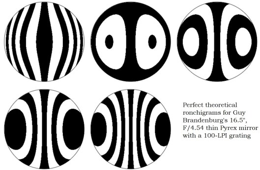
Part of the reason this mirror has taken so long is that after grinding and polishing by hand some years ago, I finally did a proper check for strain, and discovered that it had some pretty serious strain. I ended up shipping it out to someone in Taos, New Mexico who annealed it – but that changed the figure of the mirror so much that I had to go back to fine grinding (all the way back to 120 or 220 grit, I think), and then re-polishing, all by hand. I tried to do all of that, and figuring of the mirror, at one of the Delmarva Mirror Making Marathons. It was just too much for my back — along with digging drainage ditches at Hopewell Observatory, I ended up in a serious amount of pain and required serious physical therapy (but fortunately, no crutches), so this project went back into storage for a long, long time.
Recently I’ve tried more work by hand and by machine. Unfortunately, when I do work by hand, it seems that almost no matter how carefully I polish, I cause astigmatism (which I am defining as the mirror simply not being a figure of rotation) which I can see at the testing stand as Ronchi lines that are not symmetrical around a horizontal line of reflection. (If a Ronchi grating produces lines that look a bit line the capital letters N, S, o Z, you have astigmatism quite badly. If astigmatism is there, those dreaded curves show up best when your grating is very close to the center of curvature (or center of confusion) of the central zone.
Using this machine means controlling or guessing at a LOT of variables:
Here is a sketch of how this works

08 Saturday Sep 2018
Posted in astronomy, flat, Hopewell Observatorry, optical flat, Optics, Telescope Making
Tags
Astro Bananas, cassegrain, couder, double pass auto collimation, ealing, foucault, Hopewell Observatory, matching Ronchi, Mel Bartels, Ronchi, ronchigram
The other regulars and I at the DC ATM group at the CCCC have been trying to test a 12 inch Cassegrain mirror and telescope manufactured nearly 50 years ago by a company called Ealing and currently owned by the Hopewell Observatory, of which I am a member. It hasn’t been easy. I discussed this earlier on Cloudy Nights.
Reports from several people, including Gary Hand and the late Bob Bolster, indicated that the optics on this mirror weren’t good at all. Apparently the folks at the University of Maryland’s observatory were sufficiently unhappy with it that they either sold it or gave it to National Capital Astronomers, a local astronomy club, who in turn gave it or sold it to Hopewell Observatory.
With a plain-vanilla Ronchi test, we could see that the mirror was very smooth and continuous, with no turned edge, astigmatism, or bad zones. With the Foucault/Couder zonal test (aka “Foucault” test) , I got results indicating that it was seriously overcorrected: some sort of hyperboloid, rather than the standard paraboloid characteristic of classical Cassegrain telescopes, which have a parabolic primary mirror and a hyperbolic secondary mirror.
However, I have begun losing my faith in my zonal readings, because they often seem to give results that are way out of whack compared to other testing methods.
So we decided to do some additional tests: the Double-Pass Auto-Collimation (DPACT) test used by Dick Parker, as well as the Matching Ronchi test (MRT).
The DPACT is very fiddly and exacting in its setup. We used (and modified) the setup lent to us by Jim Crowley and illustrated by him at his Astro Bananas website. Our results seem to show that the mirror is in fact NOT parabolic, rather, overcorrected, which confirms my Foucault measurements. If it were a perfect paraboloid, then the ronchi lines would be perfectly straight, but they definitely are NOT: they curve one way when inside the focal point, and curve the other when the tester is outside the focal point.
We also tested the entire setup on a radio tower that was about half a mile (~1km) distant. We found that the images were somewhat blurry no matter what we did.
We also attempted the MRT on the same mirror. However, requires very accurate photography and cutting-and-pasting skills in some sort of graphics programs. What you are inspecting is the curvature of the Ronchi lines. Here is the result that Alan T and I got last night:

In black is the ideal ronchigram for this mirror, according to Mel Bartels’ website. The colored picture is the one we made with either my cell phone or the device I finished making earlier this week, shown in my previous post. Here are the two images, separated rather than superimposed:


The mirror’s focal length is 47.5″ and the grating has 100 lines per inch, shown somewhat outside of the radius of curvature. The little ‘eyelash’ on the lower left is simply a stray wire that was in the way, and doesn’t affect the image at all. The big hole in the middle is there because the mirror is a cassegrain.
I don’t know about you, but I don’t really see any differences between the real mirror and the theoretical mirror. Do you?
So, what does this all mean?
07 Friday Sep 2018
Posted in astronomy, Optics, science, Telescope Making
Tags
brightness, color balance, exposure, focus, foucault, gain, knife edge, Ronchi, testing, webcam
Here is the latest incarnation of my webcam Ronchi and knife edge (or Foucault) tester. It’s taken quite a few iterations to get here, including removing all the unnecessary parts of the webcam. I attach a still photo and a short video. The setup does quite a nice job of allowing everybody to see what is happening. The only problem is setting the gain, focus, exposure, brightness, color balance, contrast, and so on in such a way that what you see on the screen resembles in any way what your eye can see quite easily.

30 Thursday Aug 2018
Posted in astronomy, nature, Uncategorized
On September 30, members of the public will have the opportunity to observe several planets, the moon, and other heavenly objects through some telescopes to be provided by local amateur astronomers, including members of NCA and NOVAC, at the lovely Lake Artemisia Natural Area in Berwyn Heights, MD.
The location has a wide open southern horizon over the lake, and is surprisingly well-shielded from lights from local highways and shopping centers. The address is
Normally this park closes at sunset, but it will remain open for this event, which is scheduled for 7:00 (just about sunset) to 11:00 pm (just after moonrise) on Sunday evening, September 30. The event is free. I’ve attached a couple of maps. Please note that Berwyn Road dead-ends at the Metro rail lines.


We should be able to see Venus, Jupiter, Saturn, Mars, and the rising Moon, if weather permits. Volunteers with telescopes would be appreciated!
27 Tuesday Mar 2018
Posted in astronomy, Math, Optics, Telescope Making, Uncategorized
Tags
By Guy Brandenburg
3/27/2017
I describe here an attempt to quantify progress (or lack thereof) in the removal of the classic, and dreaded, turned-down edge (TDE) present on a 16.5” Newtonian glass mirror blank that I have been trying to “figure” for some years. The figuring process means changing a piece of glass that approximates a small section sliced out of a large hollow sphere, into a highly-accurate paraboloid — with the required level of accuracy being measured in nanometers.
Many amateur and professional telescope makers have maintained that you can only fix figuring errors if you can measure them. Not being able to get good, repeatable measurements of the TDE on my mirror, I had been sort of floundering, failing to get rid of the TDE even after YEARS of work (off and on; mostly off). So a decision was made to try to quantify things.
We recently had some success in matching computer-generated Ronchi images of theoretically-perfect mirrors with photos taken of works in progress, simply by cutting and pasting – which has been recommended by Mel Bartels in particular for quite some time. For the first time, I got the hang of it, and we were able to help a first-timer (Mike L) to figure a 10” plate glass f/5.4 mirror only ¾” thick to just about exactly ¼ lambda, according to our combined, repeated, careful measurements on a mirror that was cooled both by immersion in a room-temperature water bath and by sitting in a closet in the very same testing room for an entire weekend.
Prior to this experiment, I had been taking short videos of the entire mirror, moving the ronchi grating back and forth across the center of curvature. These videos reveal and record a lot of qualitative information about the mirror, including vocal commentary, but I found it impossible to transfer the images to my laptop for closer analysis until I got home, across town, which meant that the turn-around time after testing a mirror was much too long to be of any use. I had tried quite a large number of various strokes suggested by others, by our reading various ATM manuals, and by just thinking; but the very serious TDE on this (for me, relatively ambitious) project never seemed to get any better.
I simply gave up on imaging via video clips, since they were too hard to manipulate or measure on my phone, and which required too much bandwidth to send to my laptop until I got home. This time, I took Ronchi still-images on my cell phone, between 0.2 and 0.5 inches outside of the center of curvature.

(My experience has been generally easier to discern defects in a Ronchigram when the lines curve outwards at the top and bottom, which would mean the test grating is OUTSIDE the COC of a partly-parabolized mirror, as you see on the left in the black-and-white image above. However, when the lines curve inwards at the top and bottom, like the images in the center and to the right, then many serious defects remain hidden. 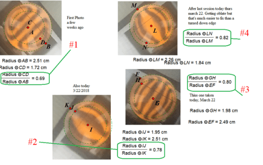
Procedure:
A standard 100 LPI grating from Willmann-Bell and a yellow LED were used, on an XYZ stage partly fabricated by me and placed exactly twice the focal length from the primary. Images were taken with an iPhone 6, shooting images zoomed in as much as possible. An attempt was made to have matching ronchigrams, i.e., with the same number of vertical lines showing.
(This was a weak point of the experiment. For one, it’s hard to hold cell phone steady enough, and an observer will notice that the images do NOT have exactly the same number of lines. That’s because I did not have a printout of the previous image right in front of me to make comparisons to. All that needs to be fixed in subsequent iterations. Also, other imaging devices need to be tried, as well.)
I was in fact able to email individual photograph frames to my laptop at the lab. After downloading the clearest images to my laptop, I used plain old MS Windows Paint to shrink and crop the useful portion of the picture, and then pasted the result into a Geometry software (Geometer.s Sketchpad, or GSP) that I was already familiar with. GSP was then used to draw a circle around the circumference of the image of the nearly-perfectly-circular glass disk, adjusting this as well as possible. This process automatically generated the center of the disk. Using that center, a second, and smaller, circle was drawn whose circumference was placed at the location along the ronchi lines where they appeared to begin to turn outwards. GSP was then to measure directly the radii of the two circles and to compute their ratio.
A final ratio of 0.7, just to pick a number that is easy to compute, means that just about half of the area of the mirror is covered by a wide rolled-down edge, since the ratio of areas is equal to the square of the ratio of the respective radii, and 0.7 squared is 0.49, or 49%.
In the diagram above, the images go in chronological order but COUNTER-clockwise, from upper left (labeled #1), which was made in mid- or early March, through the next three images, all taken on March 22. In between each image, various strokes were employed in figuring sessions for anywhere between 15-20 minutes to attempt to fix the TDE. All the figuring sessions involved sub-diameter laps anywhere from 8 to 12 inches in diameter that had been warm-pressed upon the mirror. The strokes were both forward and back and incorporated enough of a ‘W’ stroke to cover the entire mirror, using cerium oxide on either tempered burgundy or Acculap pitch, depending. The edge of the tool was allowed to go up to the edge of the mirror, +/- maybe 5 mm. The goal was simply to wear down the glass in the center until it caught up with the amount that the edge had been worn down. None of the laps seemed to have full contact with the mirror out to the very edge; thus the end of the stroke was NOT at the edge of the mirror.
You will notice that these ratios, circled in green, seem to increase monotonically from 69% to 80%, which is gratifying: if this real, then the fraction of the mirror that is NOT covered by TDE has gone from about 47% to about 67%, as you can see here. (Note: in figure #1, the large circle was denoted circle AB, and the smaller circle was denoted circle CD. I know that points A and C are not identical, but they are rather close; that error will be fixed in subsequent iterations.)
However: the key question is: IS THIS REAL? Or am I merely fooling myself?
I don’t know yet.
I certainly hope it is real.
But it needs to be checked with subsequent investigation.
My attempt at limiting my own subjectivity or wishful thinking was to try to draw the circles at the place where the more-or-less vertical lines began turning outwards. Hopefully that location really corresponded to the place where the turned/rolled edge began. However, it is entirely possible that the precise apparent location of the beginning of the TDE very much depends on exactly how many lines appear in the Ronchigram, thus, precisely how far from the COC the grating is located.
Unfortunately, often times I have to dismantle the entire apparatus, because we have to close up shop for the night, or somebody else needs to use the tester on another mirror. Thus, it is nearly impossible to ensure that the measurement apparatus remains undisturbed.
My next steps, I think, are these:
I would like to thank Isaac and Elias Applebaum for their diligent and noted explorations in solving a similar question relating to fixing or preventing TDE. That STEM project won them a number of well-deserved awards.
05 Monday Mar 2018
Just got back from an exciting astro expedition to Hopewell Observatory with one of the other members. Great fun!
Anybody living on the East Coast in March 2018 has just lived through a very strong, multi-day gale. The same weather system brought snow and flooding to the northeast, and here in the DC-Mar-Va area, it was cut off power to many (including my mother-in law) and caused almost all local school districts to close — even the Federal Government! Two of my immediate neighbors in DC had serious roof damage.
Today, Sunday, Paul M and I decided the wind had calmed enough, and the sky was clear enough, for an expedition to go up and observe. We both figured there was a good chance the road up to the observatory would be blocked by trees, and it turns out that we were right. My chainsaw was getting repaired – long story, something I couldn’t fix on my own – so I brought along work gloves, a nice sharp axe, loppers, and a 3-foot bowsaw. We used all of them. There were two fairly large dead trees that had fallen across the road, and we were able to cut them up and push them out of the way.


However, there was a large and very dangerous ‘widow-maker’ tree (two images above) that had fallen across the road, but it was NOT on the ground. Instead, was solidly hung up on the thick telecommunications line at about a thirty-degree angle to the ground. The power lines above it didn’t seem to be touched. You could easily walk under the trunk, if you dared (and we did), and you probably could drive under it, but of course the motion of the car just might be enough to make it crack in half and crush some unlucky car and its driver. Or maybe it might make the phone line shake a bit …
No thanks.
So, we didn’t drive under.
I called the emergency phone for the cell phone tower (whose access road we share) to alert them that the road was blocked and could only be cleared by a professional. I also attempted to call a phone company via 611, without much success — after a long wait, the person at the other end eventually asked me for the code to my account before they would forward me to somebody who could take care of it. Very weird and confusing. What account? What code? My bank account? No way. We will both call tomorrow. Paul says he knows some lawyers at Verizon, whose line he thinks it is.
But then: how were we going to turn the cars around? It’s a very narrow road, with rocks and trees on one side. The other side has sort of a ravine and yet more trees. Paul realized before I did that we had to help each other and give directions in the darkness to the other person, or else we would have to back up all the way to the gate! Turning around took about four maneuvers, per car, in the dark, with the other person (armed with astronomer’s headlamp, of course) yelling directions on when to turn, how much to go forward, when to stop backing up, and so on. Success – no injuries! We both got our cars turned around, closed them up, got our cutting tools, gloves and hats, and then hiked the rest of the way up, south and along the ridge and past the big cell phone tower, to the Observatory buildings themselves, moving and cutting trees as we went.
As we were clearing the roadway and walking up the ridge, we peered to the west to try to find Venus and Mercury, which had heard were now evening planets again. It wasn’t easy, because we were looking through LOTS of trees, in the direction of a beautiful multi-color, clear-sky sunset featuring a bright orange line above the ridge to our west. Winter trees might not have any leaves, but they still make the search for sunset planets rather tough. Even if you hold perfectly still, one instant you see a flash that’s maybe a planet, or maybe an airplane, and then the branches (which are moving in the breeze, naturally) hide it again. So what was it? Paul’s planetarium smartphone app confirmed he saw Venus. If the trees weren’t there, I think we also would have seen Mercury, judging by Geoff Chester’s photo put out on the NOVAC email list. I think I saw one planet.
In any case, everything at the observatory was just fine – no tree damage on anything, thanks to our prior pruning efforts. The Ealing mount and its three main telescopes all worked well, and the sky and stars were gorgeous both to the naked eye and through the scopes. Orion the Hunter, along with the Big Dog and the Rabbit were right in front of us (to the south) and Auriga the Charioteer was right above us. Pleiades (or the Subaru) was off high in the west. Definitely the clearest night I’ve had since my visit to Wyoming for the solar eclipse last August, or to Spruce Knob WV for the Almost Heaven Star Party the month after that.
Paul said that he and his daughter had been learning the proper names of all the stars in the constellation Orion, such as Mintaka, Alnilam, and Alnitak. As with many other star names, all those names are Arabic, a language that I’ve been studying for a while now [but am not good at. So complicated!] Mintaka and Alnitak are essentially the same Arabic word.
After we got the scopes working, Paul suggested checking out Rigel, the bright ‘leg’ of Orion, because it supposedly had a companion star. {Rajul means “leg”} We looked, and after changing the various eyepieces and magnifications, we both agreed that Rigel definitely does have a little buddy.
I had just read in Sky & Telescope that Aristotle (from ancient Greece) may have given the first written account of what we now call an “open cluster” in the constellation Canis Major (Big Dog – that’s Latin, which I studied in grades 7 – 12) called Messier-41, only a couple of degrees south of Sirius, the brightest star in the sky. A passage in a book allegedly written by Aristotle (roughly 230 BC) seems to indicate that he could see this object with averted vision. (He was trying to establish that it was a fuzzy patch in the sky that was most definitely NOT a comet, just like Charles Messier was doing almost exactly two thousand years later!)
M41 was quite attractive. But no, we didn’t then look at M42. Been there, done that many times before. And no, what you see with a telescope does not have all those pretty colors that you see in a photograph.
Instead, we looked on a multi-sheet star atlas (that stays in the observatory) near M41 and found three other open clusters, all really beautiful. We first found M38 and thought that in the C-14 and 6″ Jaegers, it looked very anthropoid or like an angry insect, if you allowed your mind to connect the beautiful dots of light on the black background. In the shorter 5″ refractor made by Jerry Short, it looked like a sprinkling of diamond dust. This cluster must have been formed rather recently. We then found M36, which was much less rich, but still quite pretty. Lastly, we found M37, another open cluster, which has a very bright yellow star near the center, against background of much fainter stars. It seemed to me that those other stars might be partly obscured by a large and somewhat translucent cloud of dust. We saw a web of very opaque dust lanes, which we confirmed by readings on the Web. Really, really beautiful. But I’m glad we don’t live there: too dangerous. Some of the stars are in fact red giants, we read.
Then we looked straight overhead, in the constellation Auriga. We decided to bypass the electronics and have Paul aim the telescope, using the Telrad 1-power finderscope, at one of the fuzzy patches that he saw there. He did, and my notes indicate that we eventually figured out that he found Messier-46 (yet another open cluster) with his naked eye! Very rich cluster, I think, and we even found the fan-shaped planetary nebula inside!
At this point we were getting seriously cold so we moved over just a little, using the instruments, to find M47, again, a very pretty open cluster.
Realizing that the cold and fatigue makes you do really stupid things, and that we were out in the woods with no way to drive up here in case of a problem, we were very careful about making sure we were doing the closing up procedures properly and read the checklist at the door to each other, to make sure we didn’t forget anything.
On the walk back, we saw the Moon coming up all yellowish-orange, with the top of its ‘head’ seemingly cut off. When it got a bit higher, it became more silver-colored and less distorted, but still beautiful.
I really thought all of those open clusters were gorgeous in their own right, and I think it would be an excellent idea to make photographs of them, but perhaps black dots on white paper, and give them to young folks, and ask them to connect the dots, in whatever way they feel like doing. What sorts of interesting drawings would twenty-five students come up with?
I am not sure which of our various telescopes would do the best job at making astro images. I have a CCD camera (SBIG ST-2000XM), with a filter wheel. What about just making it a one-shot monochromatic black and white image? I also have a Canon EOS Revel XSI (aka 450D, I think). Compare and contrast… The CCD is really heavy, the Canon quite light. I also have a telephoto lens for the Canon, which means that I have essentially four telescopes to choose from (but not a big budget!). One problem with the C-14 and my cameras is that the field of view is tiny: you can only take images of very small bits of what you can see in the eyepiece with your naked eye. This means you would need to make a mosaic of numerous pictures.
In any case, no imaging last night! Not only did I not feel like hauling all that equipment for a quarter of a mile, after all that chopping, sawing, and shoving trees, it turns out I had left my laptop home in the first place. D’oh!
I had previously found every single one of these open clusters when I made my way through the entire Messier list of over 100 objects, with my various home-made telescopes, which had apertures up to 12.5 inches. However, I don’t think I had ever seen them look so beautiful before! Was it the amazing clarity of the night, or the adventure, or the company? I don’t know!
But this was a very fun adventure, and this photography project – attempting to make decent images of these six open clusters – promises to be quite interesting!

