• My series on making a Newtonian telescope
  • How Leon Foucault Made Telescopes

Guy's Math & Astro Blog

Guy's Math & Astro Blog

Category Archives: Telescope Making

A ‘Maker Faire’ in Reston, VA

15 Tuesday Mar 2016

Posted by gfbrandenburg in astronomy, Telescope Making

≈ Leave a comment

Tags

make, maker faire

I went to a “mini maker Faire” in Reston mostly as an exhibitor (on telescope making, hence the home made scopes) but also had a bit of time to visit with other “makers” before the gates opened.

The silly little ears are from a gizmo that was supposed to read and interpret brain waves … either my head was too thick or I broke the gizmo or I am dead: It couldn’t read my brain waves.

It was fun, and I talked to a lot of very interesting people. I regret that I didn’t take Jeff Guerber up on his offer to staff my tables while I went and looked at the other exhibits. Two entire, enormous, modern NoVa public schools (a MS and a HS) were filled with exhibits on all kinds of crafts. Lots of 3D printers, physics stuff, including jugglers in my hall. I have no idea what was in the other ones!

I met a high school girl who had a T-shirt proclaiming her desire to become a mason. She told me she was well aware that there were very few (if any) female masons. I applaud her goal and hope she is successful!

IMG_4321
IMG_4318
IMG_4317
IMG_4319
IMG_4323

Another recent scope at the NCA – ATM workshop at the CCCC

11 Friday Mar 2016

Posted by gfbrandenburg in astronomy, Telescope Making

≈ Leave a comment

Tags

ATM, CCCC, NCA

This ultra-short scope, by Todd M, has a mirror of 4.25″ (108 mm) and a pretty short focal length – about 2 feet (60 cm). He made just about everything, right here in the NCA ATM workshop at the Chevy Chase Community Center. He ground, polished, figured, and even helped aluminize the primary mirror; made the primary cell AND the spider and secondary holder; made all of the rest of the mount that you see; and even made the focuser itself from some plumbing parts!

IMG_4104
IMG_4106

It’s a very nice job, meriting a lot of praise. In case you were wondering, the paint was a special, very-high quality and very expensive top-of-the-line alkyd enamel, costing about $200 per gallon – and we have two of them. Explanation: it was an ‘oops’ can that was specially ordered and mixed for someone who changed their mind and couldn’t return it. In exchange for a non-profit donation receipt in the name of NCA, Bill R was able to get the person to donate both gallons to us.

The spider and secondary holder are very similar to the one made by Ramona D that you can see here. The major differences are:

(1) Todd used busted bandsaw blades rather than steel strapping tape for the vanes. (Both were the same price: free.) After looking at both projects, which both turned out quite nicely, my conclusion is that if you want to use bandsaw blades, you have to heat-treat (anneal) them so they will have less of a tendency to break right at the location where you are trying to bend them by 45 degrees. (Heat it up to cherry red and then let it cool slowly in the air, making it softer and less brittle, I am told…)

(2) And of course, it certainly helps to grind down the teeth of the bandsaw blade both for safety and to reduce weird reflections. Strapping tape is about the same thickness as many band saw blades, but the tape is wider and hence more stable and less prone to turn crooked (I think).

(3) Todd used ordinary 1/4″-20 machine screws (aka bolts) to attach the vanes of the spider to and through the walls of the tube. He cut off the heads of the bolts and ground one side flat near the head, and then drilled a little hole in that flat part, tapped (threaded) that, and used a tiny little machine screw to attach the vane to the specially-prepared screw, in a process that I hope is clearly shown in these three drawings.

Begin with a machine screw (bolt)
Cut off the head, use a grinder or saw to make a flat area (or else you can split the screw down the middle)
Drill and tap (i.e., thread) the little hole; attach to vane; feed the far end through a hole in the wall of the tube; attach securely with a washer and nut.

(4) Ramona, however, used thumbscrews instead of doing all that cutting, filing and tapping. Actually, our little tiny tapping drills didn’t play well with our bit holders – they kept slipping. So she just drilled holes in the center of each thumbscrew head, and bought three very small nuts and bolts and used them in the place of the little screw that Todd used.

(Thumbscrews like these:)

thumbscrews

One Way to Make a Telescope Spider

05 Saturday Mar 2016

Posted by gfbrandenburg in astronomy, Telescope Making

≈ 4 Comments

Tags

ATM, diagonal, dobsonian, spider, Telescope

All Newtonian telescopes require a secondary mirror — a flat mirror held at roughly a 45-degree angle to reflect the light from the primary out to the side. Generally this secondary mirror is an ellipsoid, in order to waste as little light as possible.

One major problem is figuring out how to hold this secondary mirror in place securely without interfering with the passage of light from your distant target. The secondary mirror can be held on a stalk, or on crossed arms like a spider’s web.

The images below show how Ramona D made a spider using a piece of extruded aluminum tube with a square cross section, several bolts, a spring, a piece of plastic dowel, some pieces of steel strapping tape, a few thumbscrews, and various small nuts and bolts. She did a very neat job, including threading and tapping several small holes in the aluminum tube.

The idea is not original to me: I got the idea from somebody else on line, but unfortunately, I don’t recall the name of the person to whom I should give credit.

Here are some photos that probably do a better job of explaining how to make it than I could explain in many, many paragraphs.

ramonas spider 1.png

ramonas spider 2

ramonas spider 3

ramonas spider 4

A recently-completed telescope

27 Saturday Feb 2016

Posted by gfbrandenburg in astronomy, Telescope Making

≈ Leave a comment

Tags

CCCC, dobsonian, Telescope

Steve S recently finished a telescope with help from the DC-area amateur telescope making (ATM) workshop that I’ve been running at the Chevy Chase Community Center (CCCC) for several years (I took over from the late Jerry Schnall around the turn of the century) with help from several local ATMers and under the auspices of the National Capital Astronomers (NCA).

Steve had made the mirror quite a long time ago (not here in DC). The optics are quite good according to my tests, and if you look at the photos, I think you will agree that the body of the telescope looks excellent as well.

IMG_4177
IMG_4178
IMG_4179

IMG_4184

steve suranovic's scope 5
steve's scope 6

IMG_4183

As you can see, he used more-or-less dimensional wood rather than the more conventional plywood. Or should I say, clear pine that had been glued into boards at the lumber factory. He made the cradle with a bolt that allows one to loosen or tighten the grip on the tube so that one can rotate it or shift it forward or back to take care of any changes in balance.

It may not be obvious, but the wood is in fact coated with varnish.

The rocker box is held onto the azimuth bearing with sturdy wingnuts so that it can be more easily transported. The two circular sections of the azimuth bearing were table tops purchased at Lowe’s (IIRC).


Telescope Making in Cuba?

04 Friday Dec 2015

Posted by gfbrandenburg in Telescope Making

≈ Leave a comment

Tags

ATM, cuba, dobsonian, Grit, Mirror, Optics, Polishing, Telescope

Inspired by a Canadian amateur astronomer who visited the place, I’ve been in recent contact by email with some potential amateur telescope makers in Cuba. 
 .
I proposed bringing the optics for some completed 4″ to 8″ Newtonian telescopes in my luggage (ie parabolized & aluminized mirrors, diagonals, and eyepieces) and then giving them ideas and assistance on making the rest of the scopes. I have a number of already-completed primaries and diagonals at our DC telescope making workshop, but would have to scrounge around for eyepieces. 
 .
(If mechanics in Cuba can keep 1958-model cars running for over 50 years, I bet that they can probably improvise other stuff a la John Dobson, if they have any raw materials at all, which I am not sure about). I am also not sure whether I should bring focusers and spiders, or whether they should make them there themselves…
 .
I understand from the Cubans that there are almost no telescopes in the entire country except for one no-longer-operational telescope at the University of Havana’s observatory, and certainly no Dobsonians. They sound quite interested in the idea, and also were suggesting that I might stay long enough to demonstrate how to grind and polish and figure a mirror.  If I follow up on that idea, it would probably require me bringing in abrasives and pitch in addition to the finished mirrors, which might cause further luggage problems. Explaining finished mirrors carefully wrapped up is one thing, but containers of, say, 15-micron WAO microgrit? They might cut open the bag and test to see if it’s really cocaine…. thus contaminating it…
 .
Both the Canadian and the Cubans said that bringing in materials officially labeled as ‘gifts’ would entail lots of red tape and delays.
.
For me, the payback would be the chance to practice my crappy Spanish in an exotic place that I’ve never visited, and to observe from Tropical skies that suffer relatively low light pollution, as well as doing some good in a country that seems to have a low violent crime rate…. I was planning on flying to Mexico or the Bahamas and then getting a flight to Havana, which seems cheaper than an official direct flight. I suspect that since this would be a scientific exchange, I might even be able to get both governments to sign off and issue an official visa or whatever.
 .
Any thoughts? Anybody ever been there?

Puzzlement when Trying to Figure a Convex Surface Through the Back

14 Saturday Nov 2015

Posted by gfbrandenburg in astronomy, flat, optical flat, Telescope Making

≈ Leave a comment

Tags

ATM, convex, figuring, polarizing filters, Ronchi, strain

Have you ever tried to make a convex optical surface?

If so, you know that it’s much more challenging than a concave one, since the rays of light do not come to a focus at all.

Some of us* at the Amateur Telescope Making workshop here in Washington DC have made several attempts at doing this, pretty much without success. I would like to show you some weird images that we got when we tried to ‘figure’ the convex surface by performing a Ronchi test from the back side, looking through what was supposed to be a flat.

What we find is that even though the glass itself is very clear and free of visible strain when seen by the naked eye or when using crossed polarized filters, it looks like we are looking through an extremely murky and totally un-annealed piece of ancient Venetian glass, causing all sorts of weird striations in what should otherwise be nice, smooth Ronchi lines.

These pictures go in order from outside the radius of curvature to inside the ROC.

IMG_3656 IMG_3660 IMG_3663 IMG_3665 IMG_3667 IMG_3668

You might well think that the glass itself has lots of strain left in it, causing the very weird patterns that you see here. I can prove that this is not the case by showing you a short video that we made with crossed polarizing filters of the 5-inch diameter blank itself and two pieces of plastic (the protective covers for one of the filters). Judge for yourself.

This is not the first time that this strange phenomenon has occurred.

Any suggestions from those with actual experience would be extremely welcome.

===================

* Me, Nagesh K, and Oscar O.

Great Long Weekend of Observing Near Spruce Knob, WVa at 11th Almost Heaven Star Party

18 Tuesday Aug 2015

Posted by gfbrandenburg in astronomy, Telescope Making

≈ Leave a comment

Tags

AHSP, astronomy, ATM, dobsonian, star party

I put all of my tickets (over 30!) into the raffle for a 100-degree-apparent-field-of-view eyepiece at AHSP but didn’t win it. I probably should have put a few tickets in some other raffles. They had a whole lot of different stuff being raffled off. The eyepiece I wanted was donated by Hands On Optics. At AHSP they give you ten tickets as part of your registration, and then you can buy more of them. Elizabeth Warner and her husband left the morning of the raffle (Sunday) and gave me theirs, which was very nice of them.

At Stellafane, they used to have just ONE humongous item in the raffle, like a full set of really expensive eyepieces from Al Nagler. So it used to be in fact all-or-nothing. Don’t know if it was like that this year?
I discovered that the things I really needed were:
* an inexpensive laser collimator so I can get collimated in a minute or two all by myself, accurately, instead of fumbling around for an hour and needing an assistant… (now on order)
* an inexpensive electronic timer controller for my Canon TSi so it doesn’t need any cables to a computer (also now on order)
* a way to get rid of dew. The last night was fantastic except for the dew, which even defeated the chemical hand warmer packets that I wrapped around my finder and Telrad. I bet it got to the secondary as well. I will study up on the physics of heat production by resistors or heating wire wrapped around those and devise something.
BTW, I had to use a borrowed hack saw and masking tape to cut each of my truss tubes by exactly an inch on the second day so that I could come to a focus with all my eyepieces. I used some local rocks to deburr the cuts.
They had some great presentations on astrophotography, including how to do it simply and effectively. I was much encouraged.

Adventures in Making a Glass Surface Optically Flat

13 Friday Feb 2015

Posted by gfbrandenburg in flat, monochromatic, optical flat, Telescope Making

≈ Leave a comment

Tags

ATM, CCCC, flat, interference testing, mercury vapor, monochromatic, optical flat

I’ve been trying to make an optical flat for some time now. It’s not easy, even if you are starting with a piece of ‘float’ glass – modern 3/4″ thick window sheet glass that is manufactured by floating a layer of molten glass on a bath of molten tin.

The test apparatus consists of a supposedly-flat 12-inch diameter and a monochromatic light box, and my own gradually-increasing understanding of what the interference lines actually mean. Essentially, they are like contour lines on a topographic map, but the trick is to figure out which sections represent valleys and which ones represent hills. It’s taken help from other amateur telescope makers (particularly Philip P) and sections of Malacara’s book on Optical Testing and http://www.lapping.com .

It’s pretty amazing how we can measure stuff that is soooooo small!

Here are some photos in chronological order of my working on them. I would paste some videos but WordPress won’t allow them and I don’t feel like uploading them to YouTube. BTW: I am not done!!!

022

006

008

009

That’s me looking skeptically at my cell phone, pretending to look skeptically at the glass.010

001

Up until this point I was trying to make the flat more perfect by using a hard Gugolz lap of full size (6 inches in diameter), much as we do with parabolizing concave mirrors. I don’t think I made a whole lot of progress. Then I read some of the papers that Philip P sent me, and re-read the Malacara, and decided to think of the contour lines in terms of measures of height, and decided to use a two-inch-diameter lap only on the parts that appeared to be “high”. I marked the back of those regions with a Sharpie permanent marker (which comes off easily with isopropyl alcohol when needed) so I could see where to work and could see if what I did made any difference.flats i guess 001The places that I marked with the letter H were High spots, kind of like you see on a weather map that is plotting isobars (lines connecting places with the same barometric pressure). The lower right-hand corner was one of those places, as was the smudged region at about 9 o’clock.

BTW I got the green color by using ordinary fluorescent lamps and two carefully-selected theatrical lighting gels to filter out all the light with wavelengths either longer than or shorter than the green Mercury vapor line of 5461 Angstroms.

By the way: I’ve discovered that the 12-inch-diameter optical flat that is underneath my 6 inch test flat isn’t as flat as I thought. Boo.

Will work on this some more this afternoon.

On Making an Artificial Star for an Indoor Star Tester

04 Sunday Jan 2015

Posted by gfbrandenburg in History, Telescope Making

≈ 2 Comments

Tags

artificial star, ATM, CCCC, couder, foucault, Hubble, NCA, Ronchi, star testing, Telescope

I help run the amateur telescope-making workshop at the Chevy Chase Community Center in Washington, DC, sponsored and under the auspices of the National Capital Astronomers. Both the NCA and its ATM group have been on-going since the 1930’s, well before I was born. In our ATM group, have the somewhat esoteric thrill of manufacturing incredibly accurate scientific devices (telescopes), from scratch, with not much more than our bare hands and a few tools. And then we go and use them to observe the incredible universe we come from.

Since these telescope mirrors are required to be insanely accurate, we need extremely high-precision ways of testing them. However, we don’t have the tens or hundreds of thousands of dollars needed to purchase something like a professional Zygo Interferometer, so we use much cheaper ways of testing our mirror surfaces.

Some of those methods are associated with the names Foucault, Couder, Bath, Ronchi, Ross, Everest, and Mobsby, or are described with words like “knife-edge”, “double-pass” and “wire”. They all require some relatively simple apparatus and skill and practice in measurement and observation.

We are of the opinion that no one single test should be trusted: it’s easy to make some sort of error. (I’ve made plenty.) You may perhaps recall the disaster that happened when the Hubble Space Telescope mirror passed one test with flying colors, and other tests that weren’t so good were ignored. When the HST finally flew in orbit, it was discovered that the mirror was seriously messed up: the test that was trusted was flawed, so the mirror was also flawed.

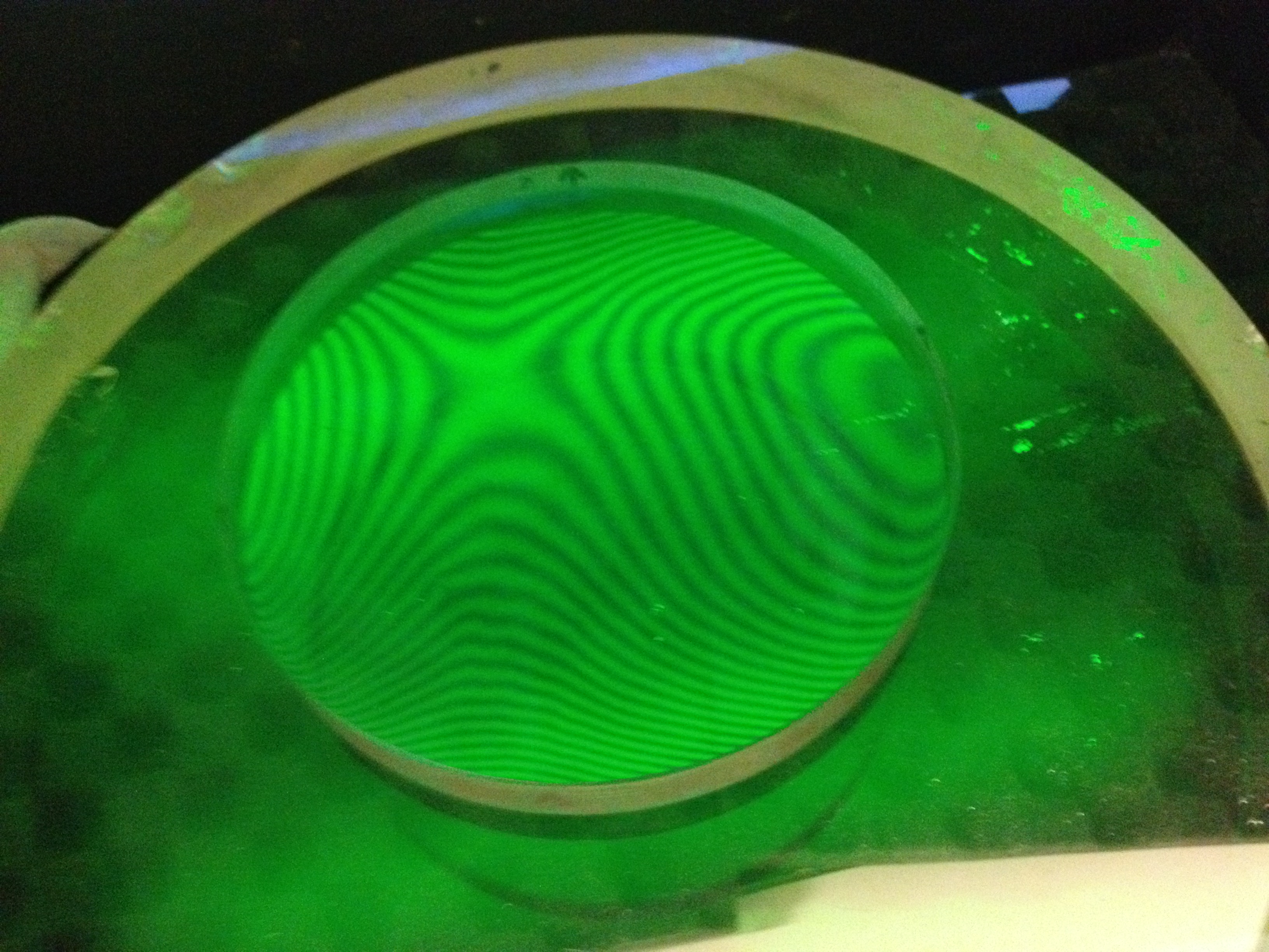
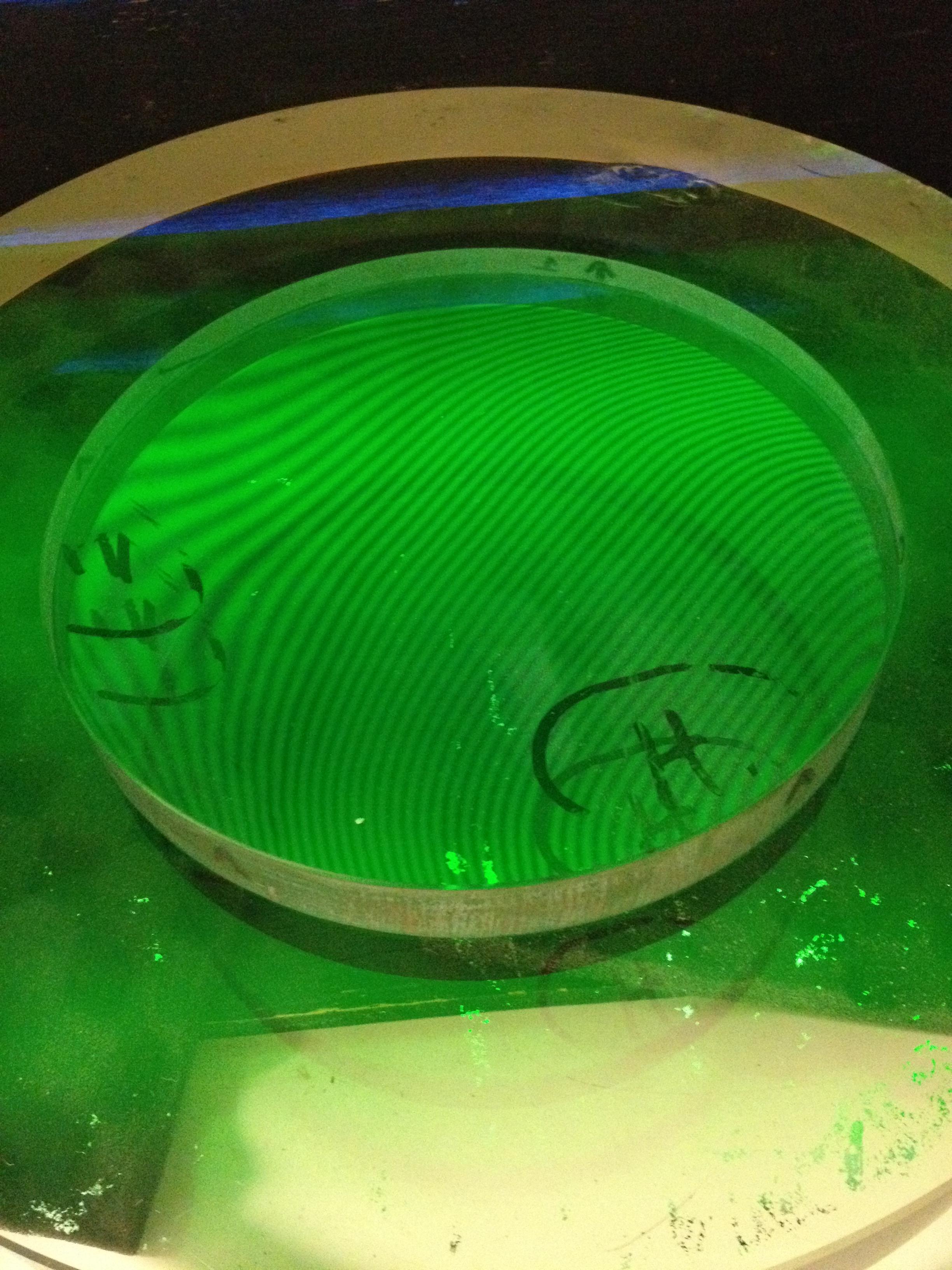
We don’t want to do that. So, at a minimum, we do the Ronchi and Foucault/Couder knife-edge tests before we say that a mirror is ready to coat.

But the ultimate test of an entire telescope is the star test.

In principle, all you need for that is a steady star, your telescope, a short-focal-length eyepiece, and a copy of Richard Suiter’s book on star-testing optical telescopes.

Unfortunately, around here, it’s often cloudy at night, and if it’s clear, it might be windy, and around the CCCC building there are lots of lights — all of which make star-testing a scope on the two evenings a week that we are open, virtually impossible. We aren’t open in the daytime, and even if we were, I don’t see any ceramic insulators on any telephone poles that are both small enough and far enough away to use as artificial stars in the manner that Suiter describes. (There are a few radio towers visible, but I doubt that their owners would let us climb up one of them and hang up a Christmas tree ornament near the top!)

So, that means we need to make an artificial star.

I’ve been reading a few websites written by folks who have done just that, and it seems to be a bit easier than I thought. The key is to get a source of light that acts like a star at astronomical distances — but close enough that we can fit it inside the basement of the CCCC, probably not in the woodshop where we make the scopes, but more likely out in the hallway or in the large activity room next door, both of which are about 40 or 50 feet long.

So here are my preliminary calculations.

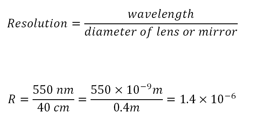
First off, it appears that the resolving power of a telescope equals the wavelength being used, divided by the diameter of the objective lens or mirror, both expressed in the same units. The result is in radians, which you can then turn into degrees, arc-minutes, arc-seconds, or whatever you like, but it’s perhaps easier to leave in radians. In any case, the larger the diameter, the tinier the angle that your telescope can resolve if it’s working properly.

I am going to use a 16-inch mirror diameter, or about 0.4 meters, as an example, and I will use green light at about 560 nanometers (560 x 10^-9 m) because that’s pretty close to the green mercury line we have in our monochromatic light box. I then get that the resolution is 1.4×10^-6 radians.

resolution of lens or mirror

(We can convert that into arc-seconds by multiply that by 180 degrees per PI radians  and by 60 arc-minutes per degree  and by 60 arc-seconds per arc-minute; we then get about 0.289 arc-seconds. If we were to use an 8-inch mirror, the resolution would be half as good, meaning the object would need to be twice as big to be resolved, or about 0.578 arc-seconds.)

resolution in arc seconds

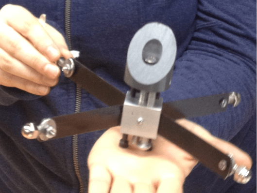
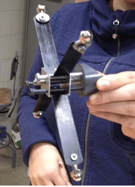
I read that one can make an artificial star by using an ordinary eyepiece and a small illuminated hole that is put some distance away from the eyepiece. The entire setup is aimed at the telescope, and then you have an artificial star. Here is the general idea:

artificial star setup

Supposedly, the equations go as follows, with all of the dimensions in the same units. I think I will use millimeters.

Star Size of artificial rigWe want to make it so that the size of the artificial star will be small enough to be below the limit of resolution of any telescope we are making. I am pretty sure that we can set things up so that there is 40 feet (13 meters) between our telescope rig and the table or tripod on which we sill set up this artificial star.

I also know that I can find an eyepiece with a focal length of 12 mm that I’m willing to use for this purpose, and I also purchased some tiny little holes from “Hubble Optics” that are of the following sizes: 50, 100, 150, 200, and 250 microns, or millionths of a meter. Those holes are TINY!!! So that takes care of H and F. I still need to figure out what SS should be.

A few lines ago, I found that for a 16-inch telescope, I need a resolution of about 1.4×10^-6 radians. The nice thing about radians is that if you want to find the length of the arc at a certain radius, you don’t need to do any conversions at all: the length of the arc is simply the angle (expressed in radians) times the length of the radius, as shown here:

angle arc radius

c=theta times Radius

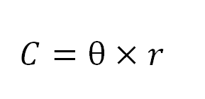
So if our artificial star is going to be 13 meters away, and we know that the largest angle allowed is roughly 1.4×10^-6 radians, I just multiply and I get 1.82×10^-5 meters, or 1.82 x 10^-2 millimeters, or 18.2 microns.

Which means that I already have holes that are NOT small enough: the 150-micron holes are about 10 times too big at a distance of 13 meters, so my premature rejoicing of a few minutes ago, was, in fact, wrong.  So, when I make the artificial star gizmo, I’ll need to figure out how to make the ‘star size’ to be roughly one-tenth the size of the holes in the Hubble Optics micro-hole flashlight.

Or, if I rearrange the equation with the L, H, F and SS, I get that L = H * F / SS. The only unknown is L, the distance between the hole and the eyepiece/lens. For H, I have several choices (50, 100, 150, 200 and 250 microns), SS is now known to be 18 microns or so (36 if I want to test an 8-incher), and I plan on using a 12.5 mm eyepiece. If I plug in the 150 micron hole, then I get that L needs to be about 104 millimeters, or only about 4 inches. Note that the longer L is, the smaller the artificial star becomes. Also, if I replace the 12.5 mm eyepiece with a shorter one, then the artificial star will become smaller; similarly, the smaller the Hubble Optics hole, the smaller the artificial star. This all sounds quite doable indeed.

One Way to Build an Alt-Az Newtonian Telescope

16 Tuesday Dec 2014

Posted by gfbrandenburg in Telescope Making

≈ 2 Comments

Tags

alt-az, dobsonian

One Way to Build a 6-inch Dobsonian-Newtonian Alt-Az Sonotube Telescope


Instructions written by Guy Brandenburg

February 2007

Acknowledgements and thanks to Mel Bartels, Richard Berry, Bill Blackmore, Jack Booth, John Dobson, David Kriege, Jerry Schnall, Jean Texereau, and many others whom I can’t remember at the moment. I have modified their ideas somewhat, hopefully for the better. However, the typos and errors are all mine.
  1. Cradle and altitude trunnions
    1. The purpose of the cradle is to hold the tube steady but also allow for changing the altitude angle and changing the balance point when additional items are added to the telescope, and to allow the user to put the focuser at a convenient angle by rotating the tube.
    2. The cradle consists of four rectangular pieces of plywood that are glued and screwed to form a box that the tube fits in, and two altitude trunnions that each consist of a plywood disk and a ring cut from a PVC sewer pipe. The pipe fits onto the plywood disk and is held there by friction. See diagram below.                           make a dob pic 1
    3. Use 2-inch deck screws, and glue, to attach the 9+3/4” by 12” pieces of plywood to the 8+1/4” by 12” pieces of plywood. Three or four screws per edge should be enough. Use plenty of glue, and use a damp paper towel to wipe up the glue that oozes out. It is not necessary to counter-sink the screws. Make sure everything is lined up properly before inserting the first screw. If you want, you can nail in a couple of small nails (say, 2” long) to hold things in place before you put in any screws.
    4. Before attaching the plywood disks that hold the PVC plastic trunnions, it is advisable to draw the diagonals as shown. This will help you make sure that the disk is centered correctly.
    5. When the glue is somewhat dry, this all can be painted, inside and out.
    6. When the paint is dry, then you can attach the handle and fit the PVC trunnions onto the plywood disks. It is supposed to go on with difficulty, so that it won’t come off easily. It should not need to be nailed, glued, or screwed.
  2. Optical Tube
    1. The tube
      1. The tube itself is made of thick cardboard designed for casting cylindrical concrete columns. One brand name for these is Sonotube. When painted, it is strong, relatively rigid and light, and reasonably waterproof, and it’s quite inexpensive: $5 for a 4-foot length of tube. (Carbon fiber composite tubes, which are lighter, stronger, more rigid and much more waterproof, would cost nearly 100 times as much.) The purpose of the tube is to hold the optical components rigidly, in the proper alignment so that the user can look at things.
      2. A 1+1/2” diameter hole will need to be drilled near the front end of the tube for the focuser. Use an ordinary hole saw attached to an electric drill for this. If you are using a 3- or 4-vane spider, measure and drill the holes for this now.            make a dob pic 2
  • It is very important to paint the inside of the tube using flat black paint. I strongly recommend using latex paint so that any drips can be washed off with water, likewise the brush, and so that the fumes are not so bad. Two or more coats are desirable. However, the tube is quite long, and you don’t want to get paint all over your arm. How to reach the middle? One way is to tape your brush to the end of a dowel rod (or other scrap piece of wood) with duct tape, and use that to extend your reach. When you have finished painting the inside, leave the tube to dry in a horizontal position so that air can circulate; or else, if you want to let it dry in a vertical position, make sure that you put it on some little scrap pieces of wood so that air can circulate up and down the tube. Be sure to wash the brush as soon as you are finished painting. Use lots of water and even some hand soap and rinse it very thoroughly.
  1. The outside of the tube also needs to be painted. Any color will do – the wilder the better, in my opinion. See the previous remarks about latex paint. It is a good idea to let the tube dry in a vertical position, propped up on little scraps of wood. Be sure to paint the edges where holes have been cut and the ends of the tube; when the loose cardboard is impregnated with paint, it becomes much harder.
  1. Primary Mirror Holder
    1. The purpose of this item is to hold the mirror rigidly in the correct alignment, at the proper distance from the secondary mirror and the focuser, so that whoever is looking through the telescope can actually see correctly-focused and clear images of whatever it is they are trying to observe. It is not necessary to paint this part, but it won’t hurt, either. However, the parts where the silicone caulk will hold the mirror to the wood must NOT be painted, because the caulk does not stick well at all to painted surfaces.
    2. The mount consists of two plywood disks separated by springs and held together by machine screws, washers, and wingnuts. The upper plywood disk has an outer diameter about one-half inch less than the inner diameter of the tube; so that’s about 7+1/2”. The lower plywood disk has an outer diameter that is about the same as the inner diameter of the tube, so that’s just shy of 8”. Each disk should have a good-size hole drilled in the center for ventilation. The size of the hole is not critical – any size that you have a hole saw for will work fine.
  • The two disks also need to have 3 holes drilled in them at 120 degrees from each other so that the machine screws can go through. The hole in the upper disk should be countersunk so that the machine screw head will not protrude. The hole in the lower disk should be considerably larger than the screw itself, so that the entire assembly can be adjusted easily. Be sure to line the two disks up together before drilling the holes, and mark how they are supposed to go.
  1. A small piece of steel (or any other convenient metal) should be fabricated into an L shape, with a hole in both parts. The hole in the horizontal part will hold a single, small screw to attach the L to the upper plywood disk, and the hole in the vertical part will be used to squirt the silicone glue through, to hold the mirror in place.
  2. When the entire setup is assembled, except for the glueing of the mirror, then lay three ordinary nails underneath where the mirror will go, as temporary spacers. Squirt nice thick blobs of glue in the three locations previously chosen, then carefully place the mirror in the correct location. Then squirt three more globs of glue, one at each of the three L-shaped edge holders. Then put the entire assembly away somewhere level, safe, and dry, with ventilation and protection from dust, so that it will not be disturbed for a couple of days while the glue sets.
  3. See the diagrams for construction details, and below that for an example by a local ATMer, JCN.                                                                    make a dob pic 3Make a dob pic 4
  • The primary mirror cell is about the last thing to be placed in the telescope. It goes in AFTER the focuser and secondary are put in place, and after everything is assembled, painted, and dried. In my experience, it is not possible to calculate exactly where the mirror should go in the telescope; none of the formulas I’ve seen work exactly. The best one can do is to estimate it, but then the exact location will depend on your eyepieces, the height of your focuser, and your eyes. So, once the rest of the scope is together, you carefully slide the primary mirror cell – with its mirror in place – up into the tube to where you think it should go, and do a very rough alignment of the mirror by looking down the tube. Use shims to get it to stay in place temporarily, and try to focus on as distant an object as possible by daylight. To get it to come into focus will probably require pushing or pulling the entire cell forward or back. Then try the entire process at night, when you can see the moon or a very bright star such as Vega or Sirius. It will not focus the same way, I guarantee! When you have the mirror in such a location that stellar objects come into focus, THEN you can use deck or drywall screws to screw it permanently into place in the tube.

make a dob pic 5cell holder variant by JCN

  1. Focuser
    1. The purpose of the focuser is to hold an eyepiece at the very end of the voyage of all of those photons from outer space so that your eye can detect an image.
    2. Unless you are doing astrophotography, a simple rack-and-pinion focuser with a knob will do just fine. The standard size focuser and eyepiece for decent, smaller telescopes (under 12” diameter) is 1/25”. Plastic-and-metal ones work fine unless seriously abused. There are ones designed for refractors, and ones designed for reflectors. Get the latter type, unless you are building a refractor!
  • Use small nuts and bolts to attach them to the telescope tube.
  1. Unfortunately, some focusers will require a shim to be fabricated underneath so that there will not be a light gap between the focuser and the telescope tube. This all depends on the focuser and the tube you are getting.
  2. As mentioned earlier, you will need to cut a hole in your tube large enough to fit your focuser.
  1. End Ring
    1. The purpose of this is to strengthen the end of the telescope tube that points towards the sky.
    2. Use a decent-quality plywood and a router to cut a ring with a thickness of roughly an inch that will fit tightly onto the end of the tube. Our tubes are 8+1/4” OD, so that should be the ID of the ring. After routing it, sand it to remove burrs and splinters, fit it onto the tube, apply some glue and small nails, and let it dry.
  • Only make an upper end ring; not a bottom end ring, or else you won’t be able to view objects near the zenith.
  1. Mid Ring
    1. The purpose of this is to allow the telescope to stay in place at the chosen balance position, and to allow the user to rotate the tube and to adjust the balance if needed.
    2. The instructions for cutting this are very much like the end ring. The difference is that there should be a small amount of ‘play’ or room for the ring to move over the tube, so that with some force and perhaps a mallet it can be moved when desired. Thus its interior diameter should perhaps be 8+5/16” when cut. Paint will reduce that slightly.
  • The mid ring is NOT glued or nailed to the tube. It should be able to slide, with difficulty.


  1. Secondary Diagonal Mirror, holder, and spider
    1. The purpose of the secondary diagonal mirror is to re-direct the light from the object of interest out the side of the telescope, so that you can see the object without your head getting in the way.
    2. You can build this or make all of these parts. Unless you are very good with your hands and with making small metal parts, I suggest you buy them. The mirror itself is a true optical flat, and is easier to make on a machine than by hand.
  • Before putting this in place, it is necessary to find the exact center of the secondary mirror, and to measure the distance from this to the level of the screws that hold the spider in place against the wall of the tube. Measure and re-measure, then drill the appropriate holes, and fasten it all in place. (Remove the mirror itself while installing the spider vanes, so that dust and fingerprints don’t get on the surface of the mirror.)
  1. Finder Scope
    1. The purpose of the finder scope is to allow the user of the telescope to aim it at an object of interest. It gives the user a wider field of view than the telescope itself, which can have a field of view as small as hundredths of a degree.
    2. I strongly suggest a Telrad or other similar 1-power non-magnifying heads-up finder. These devices allow you to aim your telescope intuitively at familiar objects and then to star-hop to other objects. Then, as your budget permits, you can upgrade to other finders – and there is a wide variety to choose from!


  1. Rocker Box
    1. The purpose of the rocker box is to hold the telescope rigidly upright and to provide a place for the altitude trunnions to fit into, so that the telescope can be aimed up and down, and left and right, just like a cannon.
    2. The rocker box is made out of 4 pieces of ¾-inch plywood. It has a front, two sides, and a bottom, but no back and no top. The front is shorter than the sides, so that the telescope can be aimed at the horizon if desired. The pieces will be glued and screwed together. The two sides will have nearly semi-circular holes cut out of the tops to hold the trunnions bearings.
    3. Need to cut out the following:
  1. Bottom: one piece 11+1/4” by 10+1/2” plywood. A one-half inch diameter hole should be drilled at its exact center.
  2. Sides: Two pieces that are 11+1/4” by 33” plywood (can be a little longer if desired). Make it so that they are left-right symmetrical, so that the good side of the plywood will be facing out. Cut an arc at the top of each side to fit the trunnions.
  • Front: One piece 11+1/4” by 25” (this height can be changed, but should be about 8 inches less than the sides)
    1. Five or six deck screws, 2” long, on each vertical edge, should be enough. Be sure to use glue as well. The bottom edges could use about 3 screws per edge. Clamp the edges for about 30 minutes after glueing, and remove excess glue with a damp rag. Except for the underneath portion, this can be painted. After drying, this will be attached to the base plate.
    2. Two pieces of Teflon will make sliding contact with the PVC trunnions. They will be glued or nailed into place at the tops of the cut-out arcs at the tops of the side pieces.

make a dob pic 6

make a dob pic 7

  1. Base Plate, or Azimuth Disk
    1. The purpose of the base plate is to allow the rocker box to swivel left and right, so that the user can aim the telescope at anything he or she wants to look at, in any part of the sky.
    2. This base plate is the invention of John Dobson, a master scrounger, all-round eccentric amateur astronomer, and former monk who lives in California. It consists of a downward-facing surface of Formica, Wilsonart, or some similar type of counter-top laminate, resting on three Teflon pads attached to an upward-facing surface. Unlike telescopes made from metal parts, this mounting rotates very smoothly and does not have any backlash at all. That is, if you move the telescope to a given position and let it go, it will stay where you leave it.
    3. To cut out:
  1. two 15-inch diameter circular disks from the same ¾” plywood. The precise size is not critical. Using the jig that we have in our shop, you need to drill a ½-inch hole at the exact center of the disks first, and then cut them out, only cutting through half of the plywood at a time, flipping them over for the second cut.
  2. One piece of countertop laminate – any type will do – a square 16” by 16” is fine.
    1. Choose which will be the upper disk, and which part of that disk will be facing up. Use paintbrush to coat the other side of the wooden disk with a smooth layer of latex-based contact cement. Also paint the back side of the countertop laminate. Let the two surfaces dry until no longer gooey to the touch. Then place the laminate on top of the wood and press hard all over (there are special rollers for this, or you can use heavy glass bottles or heavy metal cylinders) so that they make good contact.
    2. Use a trimming router to trim off the excess laminate.
    3. Then use relatively short screws to attach the top disk to the bottom of the rocker box. Make sure the hole in the bottom of the rocker box lines up with the hole in the center of the top disk. Feel free to finish drilling the center hole through the laminate.
    4. The bottom disk will receive three pieces of Teflon pad around the edges at 120-degree intervals.
  1. Legs
    1. The purpose of the legs is to give the entire telescope a bit more stability and to raise the base of the telescope up off the ground by a few inches.
    2. I suggest using a 2×3 or 2×4 and cutting three pieces about 9 to 10 inches long, then cutting them into an L-shape or a shape a bit like a hockey stick, as shown here:    make a dob pic 8
    3. File or sand the legs so that folks won’t get splinters. Make sure there is clearance for the central pivot bolt, the aluminum plate, the nuts, and the lockwasher. Position the 3 legs 120 degrees apart, then screw and glue them into place. Some of the screws will need to be rather long.
    4. Attach the Teflon pads right over the legs themselves, as close to the edge of the disks.
  1. Now paint everything and let it all dry.
  2. Align your optics.
  3. Then go observe!

(<== Link back to the beginning of this series of articles)

← Older posts
Newer posts →

Subscribe

  • Entries (RSS)
  • Comments (RSS)

Archives

  • February 2026
  • December 2025
  • November 2025
  • October 2025
  • September 2025
  • July 2025
  • January 2025
  • November 2024
  • October 2024
  • August 2024
  • July 2024
  • May 2024
  • April 2024
  • January 2024
  • December 2023
  • October 2023
  • August 2023
  • June 2023
  • May 2023
  • April 2023
  • November 2022
  • October 2022
  • August 2022
  • July 2022
  • June 2022
  • May 2022
  • April 2022
  • February 2022
  • January 2022
  • December 2021
  • October 2021
  • September 2021
  • August 2021
  • July 2021
  • June 2021
  • May 2021
  • March 2021
  • December 2020
  • October 2020
  • September 2020
  • August 2020
  • March 2020
  • February 2020
  • January 2020
  • December 2019
  • November 2019
  • September 2019
  • August 2019
  • June 2019
  • May 2019
  • January 2019
  • November 2018
  • October 2018
  • September 2018
  • August 2018
  • May 2018
  • March 2018
  • January 2018
  • November 2017
  • October 2017
  • September 2017
  • August 2017
  • July 2017
  • June 2017
  • May 2017
  • April 2017
  • February 2017
  • December 2016
  • September 2016
  • June 2016
  • May 2016
  • April 2016
  • March 2016
  • February 2016
  • January 2016
  • December 2015
  • November 2015
  • August 2015
  • July 2015
  • April 2015
  • March 2015
  • February 2015
  • January 2015
  • December 2014

Categories

  • astronomy
  • astrophysics
  • education
  • flat
  • History
  • Hopewell Observatorry
  • Math
  • monochromatic
  • nature
  • optical flat
  • Optics
  • Safety
  • science
  • teaching
  • Telescope Making
  • Uncategorized

Meta

  • Create account
  • Log in

Blog at WordPress.com.

  • Subscribe Subscribed
    • Guy's Math & Astro Blog
    • Join 54 other subscribers
    • Already have a WordPress.com account? Log in now.
    • Guy's Math & Astro Blog
    • Subscribe Subscribed
    • Sign up
    • Log in
    • Report this content
    • View site in Reader
    • Manage subscriptions
    • Collapse this bar
 

Loading Comments...