For many years now, I have been trying and (mostly) failing at using some sort of digital camera when testing the optics of the mirrors we fabricate and evaluate at the ATM workshop at the Chevy Chase Community Center here in DC.
I can now report that there finally is some useful and non-vignetted light at the end of the testing tunnel!
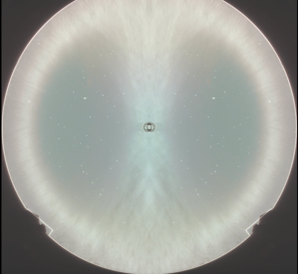
Foucault, knife-edge image, raw
Same mirror, at a different longitudinal location, image flipped right to left (ie across the y-axis), and then pasted onto the original image
Same mirror, same location as the image directly above, with circles and measurements added in Geometer’s Sketchpad
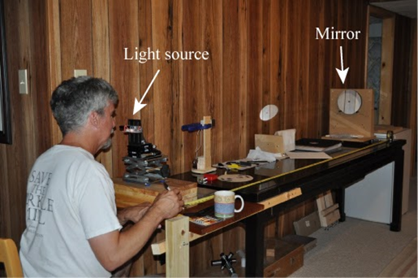
I used an old Canon FD film camera lens (FL=28 mm) that I got about 40 years ago and haven’t used in several decades to get a bunch of really nice knife-edge images of a 16″ Meade mirror, located on a stage that can be moved forward and back in whatever steps I like by a smartphone app and a stepper motor setup that Alan Tarica and Pratik Tambe designed and put together.
Just now, I finally figured out how to use IrfanView to take one of the images, flip it left-to-right (that is, across the y-axis) and superimpose one onto the other with 50% transparency. A bright ring appeared, which shows the circular ring or zone where the light from our LED, located just under the camera lens, goes out to the mirror and bounces directly back to the lens and is captured by the sensor as a bright ring.
I then captured and pasted that image into Geometer’s Sketchpad, which I used to draw and measure the radii of two circles, centered at the doughnut marking the center of the mirror. This is a somewhat crude measurement of the radii, but it appears that this zone is is at 83% of the diameter (or radius) of the original disk, which is 16 inches across.
Now I just need to do the same thing for all of the other images, and then correlate the radii of the bright zones with the longitudinal (z-axis) motion of the camera and stand, and I will know how close this mirror is to a perfect paraboloid.
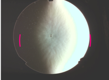
There is an app that supposedly does this for you, called Foucault Unmasked, but it doesn’t seem to work well at all. As you can see from these images, FU is unable to find zones that are symmetrically placed on either side of the center of the mirror. I don’t know what algorithm FU uses, but it sure is f***ed up.
Foucault Unmasked thinks that those two red marks are the zone being measured here. It’s pretty hard to be more wrong than that.
Again, FU at work, badly. Not quite as awful as the previous one, but still quite useless!
Thanks a lot to Tom Crone, Gert Gottschalk, Pratik Tambe, Alan Tarica, and Alin Tolea for their help and suggestions!
Several people have helped me with this applied geometry problem, but the person who actually took the time to check my steps and point out my error was an amazing 7th grade math student I know.
It involves optical testing for the making of telescope mirrors, which is something I find fascinating, as you may have guessed. Towards the end of this very long post, you can see the corrections, if you like.
Optics themselves are amazingly mysterious. Is light a wave, or a particle, or both? Why can nothing go faster than light? We forget that humans have only very recently discovered and made use of the vast majority of the electromagnetic spectrum that is invisible to our eyes.
But enough on that. At the telescope-making workshop here in DC, I want folks to be able to make the best ordinary, parabolized, and coated mirrors possible with the least amount of hassle possible and at the lowest possible cost. Purchasing high-precision, very expensive commercial interferometers to measure the surface of the mirror is out of the question, but it turns out that very inexpensive methods have been developed for doing that – at least on Newtonian telescopes.
Tom Crone, a friend of mine who is also a fellow amateur astronomer and telescope maker, wondered how on earth we can report mirror profiles as being within a few tens of nanometers of a perfect paraboloid with such simple devices as a classic Foucault knife-edge test.
He told me his computations suggested to him that the best we could do is get it to within a few tenths of a millimeter at best, which is four orders of magnitude less precise!
I assured him that there was something in the Foucault test which produced this ten-thousand-fold increase in accuracy, but allowed that I had never tried to do the complete calculation myself. I do not recall the exact words of our several short conversations on this, but I felt that I needed to accept this as a challenge.
When I did the calculations which follow, I found, to my surprise, that one of the formulas I had been taught and had read about in many telescope-making manuals, was actually not exact, and that the one I had been told was inherently less accurate, was, in fact, perfectly correct! Alan Tarica sent me an article from 1902supposedly explaining the derivation of a nice Foucault formula, but the author skipped a few bunch of important steps, and I don’t get anything like his results. it took me a lot of work, and help from this rising 8th grader, to find and fix my algebra errors. I now agree with the results of the author , T.H.Hussey.
I am embarrassed glad to say that even after several weeks of pretty hard work, an exact, correct formula for one of the commonly used methods for measuring ‘longitudinal aberration’ still eludes me. was pointed out to me by a student who took the time to Let’s see if anybody can follow my work and helped me out on the second method.
But first, a little background information.
Isaac Newton and Leon Foucault were right: a parabolic mirror is the easiest and cheapest way to make a high-quality telescope.
If you build or buy a Newtonian scope, especially on an easy-to-build Dobsonian mount, you will get the most high-quality photons for the money and effort spent, if you compare this type with any other type of optics at the same diameter. (Optical designs like 8-inch triplet apochromats or Ritchey-Chrétiens, or Maksutovs, or modern Schmidt-Cassegrains can cost many thousands of dollars, versus a few hundred at most for a decent 8″ diameter Newtonian).
With a Newtonian, you don’t need special types of optical glass whose indices of refraction and dispersion, and even chemical composition, must be known to many decimal places. The glass can even have bubbles and striations, or not even be transparent at all! Any telescope that only has mirrors, like a Newtonian, will have no chromatic aberration (ie, you don’t see rainbows around bright stars) because there is no refraction – except for inside your eyepieces and in your eyeball. All wavelengths of light reflect exactly the same –but they bend (refract) through glass or other materials at different angles depending on the wavelength.
Another advantage for Newtonians: you don’t need to grind and polish the radii of curvature of your two or three pieces of exotic glass to exceedingly strict tolerances. As long as you end up with a nice parabolic figure, it really doesn’t matter if your focal length ends up being a few centimeters or inches longer or shorter than you had originally planned. Also: there is only one curved mirror surface and one flat one, so you don’t need to make certain that the four or more optical axes of your mirrors and/or lenses are all perfectly parallel and perfectly concentric. Good collimation of the primary and secondary mirrors to the eyepiece helps with any scope, but it’s not nearly as critical in a Newtonian, and getting them to line up if they get knocked out of whack is also much easier to perform.
With a Newtonian, you only need to get one surface correct. That surface needs to be a paraboloid, not a section of a sphere. (Some telescopes require elliptical surfaces, or hyperbolic or spherical ones, or even more exotic geometries. A perfect sphere is the easiest surface to make, by the way.)
In the 1850’s, Leon Foucault showed how to ‘figure’ a curved piece of glass into a sufficiently perfect paraboloid and then to cover it with a thin, removable layer of extremely reflective silver. The methods that telescope makers use today to make sure that the surface is indeed a paraboloid are variations and improvements on Foucault’s methods, which you can read for yourself in my translation.
Jim Crowley performing a Foucault test
It turns out that the parabolic shape does need to be very, very accurate. In fact, over the entire surface of the mirror, other than scratches and particles of dust, there should be no areas that differ from each other and from the prescribed geometric shape by more than about one-tenth of a wavelength of green light (which I will call lambda for short), because otherwise, instead of a sharp image, you just receive a blur, because the high points on the sine waves of the light coming to you would tend to get canceled out by the low points.
Huh?
Let me try to explain. In my illustrations below, I draw two sine waves (one red, one green) that have the same exact frequency and wavelength (namely, two times pi) and the same amplitude, namely 3. They are almost perfectly in phase. Their sum is the dark blue wave. In diagram A, notice that the dark blue wave has an amplitude of six – twice as much as either the red or green sine wave. This means the blue and green waves added constructively.
Next, in diagram B, I draw the red and green waves being out of phase by one-tenth of a wave (0.10 lambda) , and then in diagram C they are ‘off’ by ¼ of a wave (0.25 lambda). You will notice that in the diagrams B and C, the dark blue wave (the sum of the other two) isn’t as tall as it was in diagram A, but it’s still taller than either the red or green one.
One-quarter wave ‘off’ is considered the maximum amount of offset allowed. Here is what happens if the amount of offset gets larger than 1/4:
In diagram D, the red and green curves differ by 1/3 of a wave (~0.33 lambda), and you notice that the blue wave (which is the sum of the other two) is exactly as tall as the red and green waves, which is not good.
Diagram E shows what happens is what happens when the waves are 2/5 (0.40 lambda) out of phase – the blue curve, the sum of the other two, now has a smaller amplitude than its components!
And finally, if the two curves differ by ½ of a wave (0.5 lambda) as in diagram F, then the green and red sine curves cancel out completely – the dark blue curve has become the x-axis, which means that you would only see a blur instead of a star or a planet. This is known as destructive interference, and it’s not what you want in your telescope!
But how on earth do we achieve such accuracy — one-tenth of the wavelength of visible light (λ/10) over an entire surface? And if we do, what does it mean, physically? And why one-tenth λ on the surface of the mirror, when ¼ λ looked pretty decent? For that last question, the reason is that when light bounces off a mirror, any deviations are multiplied by 2. So lambda – about 55 nanometers or 5.5×10^(-8) m- is the maximum allowable depth or height of a bump or a hollow across the entire width of the mirror. That’s really small! How small? Really insanely small.
Let’s try to visualize this by enlarging the mirror. At our mirror shop, we generally help folks work on mirrors whose diameters are anywhere from 11 cm (4 ¼ inches) to 45 cm (18 inches) across. Suppose we could magically enlarge an 8” (20 cm) mirror and blow it up so that it has the same diameter as the original 10-mile (16 km) square surveyed in 1790 by the Ellicott brothers and Benjamin Banneker for the 1790 Federal City. (If you didn’t know, the part on the eastern bank of the Potomac became the District of Columbia, and the part on the western bank was given back to Virginia back in 1847. That explains why Washington DC is no longer shaped like a nice rhombus/diamond/square.)
So imagine a whole lot of earth-moving equipment making a large parabolic dish where DC used to be, a bit like the Arecibo radio telescope, but about 50 times the diameter, and with a parabolic shape, unlike the spherical one that Arecibo was built with.
(Technical detail: since Arecibo was so big, there was no way to physically steer it around at desired targets in the sky. Since they couldn’t steer it, then a parabolic mirror would be useless except for directly overhead. However, a spherical mirror does NOT have a single focal point. So the scope has a movable antenna (or ‘horn’) which can move around to a variety of more-or-less focal points, which enabled them to aim the whole device a bit off to the side, so they can ‘track’ an object for about 40 minutes, which means that it can aim at targets around 5 degrees in any direction from directly overhead, but the resolution was probably not as good as it would have been if it had a fully steerable, parabolic dish. See the following diagrams comparing focal locations for spherical mirrors vs parabolic mirrors. Note that the spherical mirror has a wide range of focal locations, but the parabolic mirror has exactly one focal point.)
I’ll use the metric system because the math is easier. In enlarging a 20 cm (or 0.20 m) mirror all the way to 16 km (which is 16 000 m), one is multiplying 80,000. So if we take the 5.5×10⁻⁸ m accuracy and multiply it by eighty thousand you get 44 x 10-4 m, which means 4.4 millimeters. So, if our imaginary, ginormous 16-kilometer-wide dish was as accurate, to scale, as any ordinary home-made or commercial Newtonian mirror, then none of the bumps or valleys would be more than 4.4 millimeters too deep or too high. For comparison, an ordinary pencil is about 6.8 millimeters thick.
Wow!
So that’s the claim, but now let’s verify this mathematically.
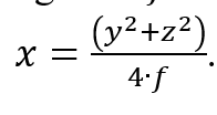
I claim that such a 3-dimensional paraboloid, like the radio dish in the picture below, can be represented by the equation
where f represents the focal length. (For simplicity, I have put the vertex of the paraboloid at the origin, which I have called A. I have decided to make the x-axis (green, pointing to our right) be the optical and geometric axis of the mirror. The positive z-axis (also green) is pointed towards our lower left, and the y-axis (again, green) is the vertical one. The focal point is somewhere on the x-axis, near the detector; let’s pretend it’s at the red dot that I labeled as Focus.)
You may be wondering where that immediately previous formula came from. Here is an explanation:
Let us define a paraboloid as the set (or locus) of all points in 3-D space that are equidistant from a given plane and a given focal point, whose coordinates I will arbitrarily call (f, 0, 0). (When deciding on a mirror or radio dish or reflector on a searchlight, you can make the focal length anything you want.)
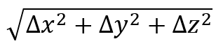
To make it simple, the plane in question will be on the opposite side of the origin; its equation is x = -f. We will pick some random point G anywhere on the surface of the parabolic dish antenna and call its coordinates (x, y, z). We will see what equation these conditions create. We then drop a perpendicular from G towards the plane with equation x = -f. Where this perpendicular hits the plane, we will call point H, whose coordinates are (-f, y, z). We need for distance GH (from the point to the plane) to equal distance from G to the Focus. Distance GH is easy: it’s just f + x. To find distance between G and Focus, I will use the 3-D distance formula:
Which, after substituting, becomes
To get rid of the radical sign, I will equate those two quantities, because FG = GH, omit the zeroes, and square both sides. I then get
Multiplying out both sides, we get
Canceling equal stuff on both sides, I get
Adding 2fx to both sides, and dividing both sides by 4f, I then get
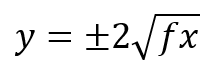
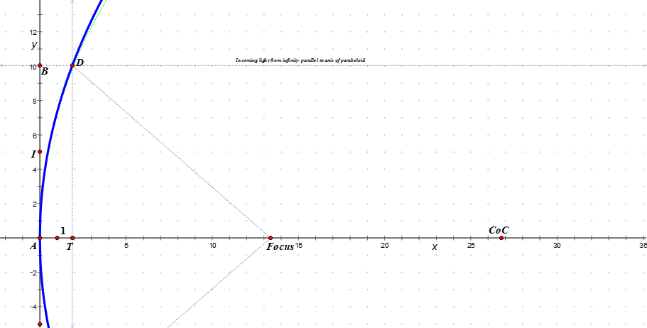
However, 3 dimensions is harder than 2 dimensions, and two dimensions will work just fine for right now. Let us just consider a slice through this paraboloid via the x-y plane, as you see below: a 2-dimensional cross-section of the 3-dimensional paraboloid, sliced through the vertex of the paraboloid, which you recall is at the origin. We can ignore the z values, because they will all be zero, so the equation for the blue parabola is
or, if you solve it for y, you get
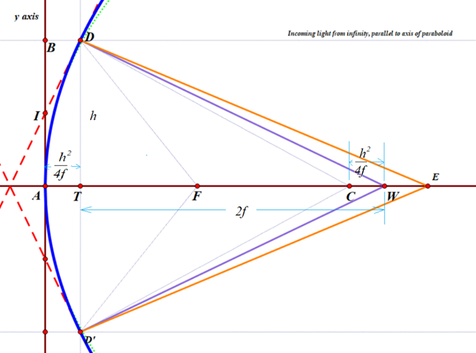
There is a circle with almost the same curvature as the paraboloid; its center, labeled CoC (for ‘Center of Curvature’) is exactly twice as far from the origin as the focal point. You can just barely see a green dotted curve representing that circle, towards the top of the diagram, just to the right of the blue paraboloid. center of the circle (and sphere). Its radius is 2f, which obviously depends on the location of the Focus.
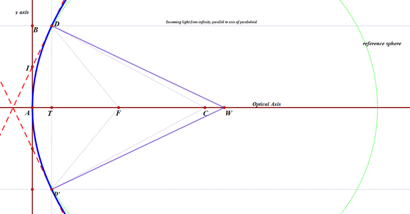
D is a random point on that parabola, much like point G was earlier, and D’ being precisely on the opposite side of the optical axis. The great thing about parabolic mirrors is that every single incoming light ray coming into the paraboloid that is parallel to the axis will reflect towards the Focus, as we saw earlier. Or else, if you want to make a lamp or searchlight, and you place a light source at the focus, then all of the light that comes from it that bounces off of the mirror will be reflected out in a parallel beam that does not spread out.
In my diagram, you can see a very thin line, parallel to the x-axis, coming in from a distant star (meaning, effectively at infinity), bouncing off the parabola, and then hitting the Focus.
I also drew two red, dashed lines that are tangent to the paraboloid at point D and D’. I am calling the y-coordinate of point D as h (D has y-coordinate -h)and the x-coordinate of either one is
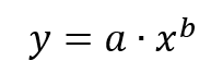
I used basic calculus to work out the slope of the red, dashed tangent line ID. (Quick reminder, if you forgot: in the very first part of most calculus classes, students learn that the derivative, or slope, of any function such as this:
is given by this:
So for the parabola with equation
the slope can be found for any value of x by plugging that value into the equation
Since
the exponent b is one-half. Therefore, the slope is going to be
which simplifies to
Now we need to plug in the x coordinate of point D, namely
we then get that the slope is
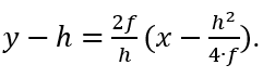
To find the equation of the tangent line, I used the point-slope formula y – y1=m(x – x1). ; plugging in my known values, I got the result
To find where this hits the y-axis, I substituted 0 for x, and got the result that the tangent line hits the y-axis at the point (0, h/2) — which I labeled as I — or one-half of the distance from the vertex (or origin) to the ‘height’ of the zone, or ring, being measured.
Line DW is constructed to be perpendicular to that tangent, so any beam of light coming from W that hits the parabola at point D will be reflected back upon itself. Perpendicular lines have slopes equal to the negative reciprocal of the other. Since the tangent has slope 2f/h, then line DW has slope -h/(2f).
Plugging in the known values into the point-slope formula, the equation for DW is therefore
Here, I am interested in the value of x when y = 0. Substituting, re-arranging, and solving for x, I get
Recall that point C is precisely 2f units from the origin, which means that the perpendicular line DW hits the x axis at a point that is the same distance from the center of curvature CoC as the point D is from the y-axis!
Or, in other words, CW = AT = DE. This means: if you are testing a parabolic mirror with a moving light source at point W, then a beam of light from W that is aimed at point D on the paraboloid will come right back to W, and the longitudinal readings of distance will follow the rule h2/(4f), where h is the radius of the zone, or ring, that you are measuring. Other locations on the mirror which do not lie in that ring will not have that property. This then is the derivation of the formula I was taught over 30 years ago by Jerry Schnall, and found in many books on telescope making – namely that for a moving light source, since R=2f,
where LA means ‘longitudinal aberration and the capital R is the radius of curvature of the mirror, or twice the focal length. So that’s exactly the same as what I computed.
HOWEVER, this formula [ LA=h^2/(2R) ] does not work at all if your light source is fixed at point C, the center of curvature of the green, reference sphere. In the old days, before the invention of LEDs, the light sources were fairly large and rather hot, so it was easier to make them stationary, and the user would move the knife-edge back and forth, but not the light source. The formula I was given for this arrangement by my mentor Jerry Schnall, and which is also given in numerous sources on telescope making was this:
that is, exactly twice as much as for a moving light source. I discovered to my surprise that this is not correct, but it took me a while to figure this out. I originally wrote the following:
But now I can confirm this, thanks in part to two of my very mathematically inclined 8th grade geometry students. Here goes, as corrected:
If one is using a fixed light source located at the center of curvature C, and a moving knife-edge, located at point E, the the rays of light that hit the same point D will NOT bounce straight back, because they don’t hit the tangent line at precisely 90 degrees. Instead, the angle of incidence CDW will equal the angle of reflection, namely WDE. I used Geometer’s sketchpad to construct line DE by asking the software to reflect line CD over the line DW.
However, calculating an algebraic expression for the x-coordinate of point E was surprisingly complicated. See if you can follow along!
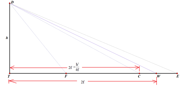
To find the x-coordinate of E, I will employ the tangent of angle TDE.
To make the computations easier, I will draw a couple of simplified diagrams that keep the essentials.
I also tried other approaches, and also got answers that made no sense. It looks like the formula in the 1902 article is correct, but I have not been able to confirm it.
I suspect I made a very stupid and obvious algebra mistake that anybody who has made it through pre-calculus can easily find and point out to me, but I have had no luck in finding it so far. I would love for someone did to point it out to me.
Hopewell Observatory is once again holding a free, public, Autumn observing session, and you are invited.
You and your friends and family can get good looks at the planets Saturn and Jupiter, as well as a bunch of open and globular star clusters. And there will be a gaggle of galaxies and double stars to look at as well.
We have a variety of permanently-mounted and portable telescopes of different designs, some commercial and some made by us, some side-by-side. Two or three people can view the same object in the sky, through different optics, with different magnifications, all at the same time! The differences can be quite amazing…
You will be capturing those photons with your own eyes, in real time, as they come to you from however far away, instead of looking at someone’s super-processed, super-long-exposure, false-color, astro-photograph (as beautiful as that image may be).
We suggest arriving near sundown, which will occur around 6 pm on 11/4/2023. It will get truly dark about 7:30 pm. The waning, last-quarter Moon won’t rise above the trees until roughly midnight. While beautiful, the Moon’s light can be so bright at Hopewell that it casts very obvious shadows, and this of course tends to make distant nebulae and our own Milky Way harder to see., so we will have many hours of Moon-free observing if the weather holds up.
If it is hopelessly cloudy and/or rainy and/or snowing, we will cancel and reschedule.
There are no street lights near our observatory, other than some dimly illuminated temporary signs we hang along the path, so you will probably want to bring a flashlight of some sort. Your cell phone probably has a decent one, but it’s better if you can find a way to cover the white light with a small piece of red plastic tape– it will save your night vision.
If you own a scope or binoculars, feel free to bring them, and you can set it/them up on our lawn.
Hopewell is about 30 miles (~45 minutes) by car from where I-66 intersects the DC beltway, but rush hour gridlock can double that time, easily. The observatory is located atop Bull Run Mountain – a ridge that overlooks Haymarket VA from an elevation of 1100 feet, near the intersection of I-66 and US-15. The last two miles of road are dirt and gravel, and you will need to walk about 250 meters/yards from where you park. We do have electricity, and a heated cabin, but since we have no running water, we have an outhouse and hand sanitizer instead.
Detailed directions are below.
Assuming good weather, you’ll also get to see the Milky Way itself, although not as well as in years past, because of ever-increasing light pollution.
If you like, you can bring a picnic dinner and a blanket or folding chairs, and/or your own telescope binoculars, if you own one and feel like bringing them. We have outside 120VAC power, if you need it for your telescope drive, but you will need your own extension cord and plug strip. If you want to camp out or otherwise stay until dawn, feel free!
If it gets cold, our Operations Building, about 40 meters north of the Observatory itself, is heated, and we will have the makings for tea, cocoa, and coffee.
Cautions
Warning: While we do have bottled drinking water and electricity and we do have hand sanitizer, we do not have running water; and, our “toilet” is an outhouse of the composting variety. At this time of year, it’s often too cold for many of the nastier insects, feel free to use your favorite bug repellent, (we have some), tuck your pants legs into your socks, and check yourself for ticks after you get home.
The road up here is partly paved, and partly gravel or dirt. It’s suitable for any car except those with really low clearance, so leave your fancy sports car (if any) at home. Consider car-pooling, because we don’t have huge parking lots.
Our Telescopes
Two of our telescope mounts are permanently installed in the observatory under a roll-off roof. One is a high-end Astro-Physics mount with a 14” Schmidt-Cassegrain telescope made by Celestron and a 5” triplet refractor by Explore Scientific. The other mount was manufactured about 50 years ago by a firm called Ealing, but the motors and guidance system were recently completely re-done by us with modern electronics using a system called OnStep, after the old gear-and-clutch system died. We didn’t spend much cash on the conversion, but it took us almost a year to solve a bunch of mysteries of involving integrated circuits, soldering, torque, gearing, currents, voltages, resistors, transistors, stepper drivers, and much else.
We could not have completed this build without a lot of help from Prasad Agrahar, Ken Hunter, the online “OnStep” community, and especially Arlen Raasch. Thanks again! (OnStep is an Arduino-based stepper-motor control system for astronomical telescopes that uses very inexpensive, off-the-shelf components such as stepper motors and their controller chips that were developed previously for the very widespread 3-D printing and CNC machining industry. The software was written by Howard Dutton. Thanks, Howard!)
The original, highly accurate Byers gears are still in place, but now it’s not just a Push-To-and-Track scope, but a true Go-To mount with very low periodic error that we can run from a smart phone! On this incredibly rugged scope mount we have two long-focal-length 6″ refractors by Jaegers and D&G, a home-made short-focal-length 5″ refractor, and a 10″ Meade SCT.
We also have two alt-az (Dob-mounted) telescopes, 10″ and 14″, both home-made, that we roll out onto our lawn, and a pair of BIG binoculars on a parallelogram mount.
Both the observatory building and the operations cabin were completely built by the hands of the original founders, starting in the early 1970s. This included felling the trees, bulldozing the clearing, planning and pouring the foundations, laying the concrete blocks, welding the observatory’s roll-off roof, and repurposing a bomb hoist to open and close that roof. Many of the founders (Bob McCracken, Bob Bolster, Jerry Schnall in particular) have passed away, but we current members continue to make improvements both small and large. In the Operations Cabin, you can see some wide-field, film astrophotos that Bolster made, and the Wright-Newtonian scope that he built and used to make those images.
Access
After parking at a cell-phone tower installation, you will need to hike south about 250 meters/yards to our observatory. Physically handicapped people, and any telescopes, can be dropped off at the observatory itself, and then the vehicle will need to go back to park near that tower. To look through some of the various telescopes you will need to climb some stairs or ladders, so keep that in mind when making your plans.
Our location is nowhere near the inky dark of the Chilean Atacama or the Rockies, but Hopewell Observatory is partly surrounded by nature preserves maintained by the Bull Run Mountain Conservancy and other such agencies, and our neighbors on both sides of the ridge have never been a problem. Unfortunately, the lights in Gainesville and Haymarket seem to get brighter every year. “Clear Outside” says our site is Bortle 4 when looking to our west (towards the mountains) and Bortle 6 to our east (back into the suburban sprawl).
DIRECTIONS TO HOPEWELL OBSERVATORY:
[Note: if you have a GPS navigation app, then you can simply ask it to take you to 3804 Bull Run Mountain Road, The Plains, VA. That will get you very close to step 6, below.]
Otherwise:
(1) From the Beltway, take I-66 west about 25 miles to US 15 (Exit 40) at Haymarket. At the light at the end of the ramp, turn left (south) onto US 15.
(2) Go 0.25 mi; at the second light turn right (west) onto VA Rt. 55. There is a Sheetz gas station & convenience store at this intersection, along with a CVS and a McDonald’s. After you turn right, you will pass a Walmart-anchored shopping center on your right that includes a number of fast- and slow-food restaurants. After that you will pass a Home Depot on the right.
(3) After 0.7 mi on Va 55, turn right (north) onto Antioch Rd., Rt. 681, opposite a brand-new housing development called Carter’s Mill.
(4) On Antioch Rd. you will pass entrances for Boy Scouts’ Camp Snyder and the Winery at La Grange. Follow Antioch Road to its end (3.2 mi), then turn left (west) onto Waterfall Rd. (Rt. 601), which will become Hopewell Rd after you cross the county line.
(5) After 1.0 mi, bear right (north) onto Bull Run Mountain Rd., Rt. 629. This will be the third road on the right, after Mountain Rd. and Donna Marie Ct. (Do NOT turn onto Mountain Road. Also note that some apps show a non-existent road, actually a power line, in between Donna Marie Ct. and Bull Run Mtn. Rd.) Bull Run Mtn Rd starts out paved but then becomes gravel, and rises steadily.
(6) At 0.9 mile on Bull Run Mountain Road, you will see a locked stone gate and metal gate, on your left, labeled 3804. That is not us! Instead, note the poorly-paved driveway on the right, with the orange pipe gate swung open and a sign stating that this is an American Tower property. We will also put up a temporary, lighted sign to Hopewell Observatory. (We have long-standing permission to use the cell tower’s access road). This is a very sharp right hand turn.
(7) Follow the narrow, poorly-paved road up the ridge to a fenced-off cell phone tower station. Drive through both orange gates. Try to avoid potholes. In places where there is a high ridge between the tire tracks, I suggest you NOT try to straddle the ridge. Instead, straddle the low spot, and drive with one set of tires riding on the high central ridge.
(8) Park your vehicle in any available spot near that cell phone tower or in the grassy area before the wooden sawhorse barrier. Then follow the signs and walk, on foot, the remaining 250 yards along the grassy dirt road, due south, to the observatory. Be sure NOT to park in such a way that your vehicle will block the right-of-way for any other vehicle.
(9) If you are dropping off a scope or a handicapped person, move the wooden barrier out of the way temporarily, and drive along the grassy track into the woods, continuing south, bypassing a white metal bar gate. (The very few parking places among the trees near our operations cabin, are reserved for Observatory members and handicapped drivers.) If you are dropping off a handicapped person or a telescope, afterwards drive your car back and park near the cell phone tower, and put the barrier back into place. Thanks.
Please watch out for pedestrians, especially children!
In the operations cabin we have a supply of red translucent plastic film and tape and rubber bands so that you can filter out everything but red wavelengths on your flashlight. This will help preserve everybody’s night vision.
The cabin also holds a visitor sign-in book; a first aid kit; a supply of hot water; the makings of hot cocoa, tea, and instant coffee; hand sanitizer; as well as paper towels, plastic cups and spoons.
The location of the observatory is approximately latitude 38°52’12″N, longitude 77°41’54″W.
A map to the site follows.
If you get lost, you can call me (Guy) on my cell phone at 202 dash 262 dash 4274 or email me at gfbrandenburg at gmail dot com.
A decade or so ago, I bought a brand-new Personal Solar Telescope from Hands On Optics. It was great! Not only could you see sunspots safely, but you could also make out prominences around the circumference of the sun, and if sky conditions were OK, you could make out plages, striations, and all sorts of other features on the Sun’s surface. If you were patient, you could tune the filters so that with the Doppler effect and the fact that many of the filaments and prominences are moving very quickly, you could make them appear and disappear as you changed the H-alpha frequency ever so slightly to one end of the spectrum to the other.
However, as the years went on, the Sun’s image got harder and harder to see. Finally I couldn’t see anything at all. And the Sun got quiet, so my PST just sat in its case, unused, for over a year. I was hoping it wasn’t my eyes!
I later found some information at Starry Nights on fixing the problem: one of the several filters (a ‘blocking’ or ‘ITF’ filter) not far in front of the eyepiece tends to get oxidized, and hence, opaque. I ordered a replacement from Meier at about $80, but was frankly rather apprehensive about figuring out how to do the actual deed. (Unfortunately they are now out of stock: https://maierphotonics.com/656bandpassfilter-1.aspx )
I finally found some threads on Starry Nights that explained more clearly what one was supposed to do ( https://www.cloudynights.com/topic/530890-newbie-trouble-with-coronado-pst/page-4 ) and with a pair of taped-up channel lock pliers and an old 3/4″ chisel that I ground down so that it would turn the threads on the retaining ring, I was able to remove the old filter and put in the new one. Here is a photo of the old filter (to the right, yellowish – blue) and the new one, which is so reflective you can see my red-and-blue cell phone with a fuzzy shiny Apple logo in the middle.
This afternoon, since for a change it wasn’t raining, I got to take it out and use it.
Two days ago, Joe Spencer had first light with the 6″ f/8 Dobsonian he built in the DC-area amateur telescope workshop. He worked hard on this project over more than a year, including grinding, polishing and figuring his mirror, and it seems to work very well.
At long last, we have finally got the venerable, massive Ealing telescope mount at Hopewell Observatory working again, after nearly 9 months, with a totally different, modern, electronic stepper motor drive based on Arduino.
My first post to the OnStep group ( https://onstep.groups.io/g/main/message/37699 ) was on October 21, 2021, over eight months ago. In it, I wrote that I had decided to give up trying to fix the electro-mechanical synchronous drive and clutches on our Ealing-Byers mount at Hopewell Observatory, and asked the folks on the OnStep message boards for help in choosing the best OnStep combination to drive such a mount.
Since then, it’s been a very long and steep learning curve. We only fried a couple of little slip-stick drivers and maybe one MaxESP board. We got LOTS of help from the OnStep list (not that the posters all agreed with each other on everything)! We ran into a lot of mysteries, especially when we found, repeatedly, that configurations that worked just fine on our workbench wouldn’t work at all when the components were put into the mount!
But now it works.
Let me thank again in particular:
* Prasad Agrahar for giving me the OnStep idea in the first place by showing me a conversion he had done;
* Alan Tarica, a fellow ATMer, for cheerfully partnering and persevering with me in working on this project for the past 8 months in many, many ways;
* Ken Hunter for providing tons of basic and advanced advice and a lot of hardware, all for free;
* Robert Benward for extremely helpful advice and drawings;
* George Cushing for providing some of the original boards we used;
* Khalid Bahayeldin for lots and lots of OnStep design features;
* Howard Dutton for designing, implementing, and supporting this whole project in the first place; and
* Arlen Raasch for bringing his wealth of trouble-shooting experience and a lot of nice equipment up to Hopewell, spending full days up there, and saving our asses in figuring out the final mysteries. Among other things, he kluged (by the way, “kluge” is German for “clever”, not clumsy) a level shifter to make it so that the 3.3 volt signals from our MaxESP3 board would actually and reliably communicate with the higher-voltage external DM542T stepper drivers that controlled the very-high-torque NEMA23 steppers, rewiring some of the jumpers on our already-modified MaxESP boards, and making the wiring look professional, and other stuff as well, thus essentially pushing us over the finish line.
* All of the Hopewell members for supporting this project
* Bill Rohrer and Michael Chesnes who physically helped out with soldering and wiring work at the observatory.
I plan to write up a coherent narrative with a list of lessons learned, and perhaps I can help make some of the step-by-step directions in the OnStep wiki a bit clearer to the uninitiated. Obviously I’ll need to write a user guide for this mount for the other Hopewell members.
If Alan and I had gone straight to our final configuration, this project would have been quite a bit cheaper. In addition to what’s inside the mount and control box at the observatory, we now have on hand something like this list of surplus items:
* four MaxESP boards in various stages of construction and functionality;
* a dozen or more different slip stick stepper drivers we aren’t using;
* four or more external stepper drivers, mostly TB6600;
* five or more stepper motors of different sizes;
* a hand-held digital oscilloscope;
* lots and lots of wires of many types;
* lots of metal and plastic project boxes of various sizes;
* lots of tiny motherboards; and
* lots and lots of sets of various mechanical electrical connectors (many were used, later cut off, and then ended up in the trash).
Yes, one does need spares, and yes, lots of this stuff has multiple uses, but this has not been a ‘green’ project. On the third hand, it has been extremely interesting and fun to learn all these new skills.
The final substantive changes that got the Ealing mount up and running were made during the Fourth of July fireworks down in the valleys on each side of the ridge that our observatory sits on. What were the changes? (1) switching the black and white leads from the mains power leads (they original, scavenged, cord had the white lead as Hot!) and (2) reversing the Declination motor direction. It also helped that I was not zoned-out and punchy from lack of sleep, as we had been when Arlen and I had last worked on it.
On July 4th, it at long last worked properly!
This Ealing mount’s original, labeled, built-in manual RA and DEC setting circles make it quite easy to put the scope into Home position before you turn on the power. One just loosens the clutches and moves the axes to 6:00 hours exactly in Right Ascension and 90 degrees exactly in Declination. From there, I found the OnStep system behaves very nicely. It accurately slewed to a number of bright, obvious targets of various sorts on both sides of the meridian. However, when I tried to get it to aim that night at M13, it refused, sending an error message that it was too close to the zenith for safety. And it was (altitude 87 degrees)! Very impressive – a safety feature I hadn’t even known about!
None of the objects that I slewed to was far from the center of the field of view, even when the scope slewed across the meridian. I was using an old, 2-inch diameter 50 mm Kellner eyepiece on an f/12 six-inch aperture D&G refractor.
I found that the Android app to be **much** better for initial setup than the SHC. Arlen, Alan and I all found that setting the correct latitude, longitude, UTC offset and so on from the SHC was a real brain-twister because of its unfortunately not-very-friendly user interface. Using the OnStep app on a cheap, old Android tablet made the whole initialization process very much easier and faster, especially after I let the tablet discover what time it really was from my iPhone’s wireless HotSpot.
However, I found that the hand paddle is much better for fine-tuning of pointing and so on, because the bright display on an Android, no matter how dim one makes it, will destroy one’s night vision, and one cannot reliably feel where the directional buttons are on a flat screen while staring through an eyepiece. Obviously, one can feel the buttons on the SHC quite well, maybe even with gloves. A joy stick would be even better…
Alan and I and the other Hopewell members still have many more OnStep features to learn.
However: if I had known this project would take over eight months of hard work, I think I might have tried fiddling with the original Ealing clutches some more.
Oh well, we have a mount that has much more capabilities than it ever had, and Alan and I have learned quite a bit of electronics! I’m proud of what we did!
For many months, we members of The Hopewell Observatory have been doing our best to repair the 50 year-old clock drive on our university-grade Ealing telescope mount.
Yesterday, after a lot of help from others, I finally got it to work — at least in the day time. With no telescopes mounted on it. And 100% cloud cover. So I really don’t know for sure.
We still need to test it out on a clear night, to see how well it tracks and finds targets.
I think I will re-configure the wiring so that it fits in a box outside the mount, instead of using the weirdly-shaped compartments inside: one needs to do occasional maintenance on the OnStep hardware and software, and none of that is easy to access right now.
I think I have figured out what was going wrong with our OnStep build:
Our unmodified Arduino-based, green, MaxESP3.03 OnStep micro-controller unit board had two major errors: it didn’t put out any signal at all in the Enable channel in either Right Ascension or in Declination, and in Declination, the Step channel didn’t work either. (I can only guess what caused this, or when it happened, but these errors explain why we couldn’t get this particular board to work any more.)
We had the connecting wires between the two blue, modified boards of the same type and the external TB6600 stepper drivers in the wrong arrangement. We stumbled upon a better arrangement that Bob Benward had suggested, and indeed it worked!
I never would have figured this out without the nice hand-held digital oscilloscope belonging to Alan Tarica; his help and comittment to this project; advice from Ken Hunter that it was a bad idea to have the boards and stepper drivers connected, because the impedance of the motors makes the signal from the board too complicated, and also the signals to the motors themselves are extremely complex! Let me also thank Bob Benward for making beautiful and elegant schematics from the drawings I’m making with pencil and eraser on a couple of 11″x17″ sheets of stiff art paper and pointing out the anomalies between our (Ken’s? I thought I was faithfully copying his arrangements….) original wiring connections and what the manual recommends.
I’m puzzled that our earlier arrangement worked at all. Given that this oscilloscope sees extremely complex, though faint, voltage curves from my own body (anywhere!), I am guessing that electrical interference fooled the drivers into sending the correct commands to the stepper motors even though the STEP and the DIRECTION wires were crossed.
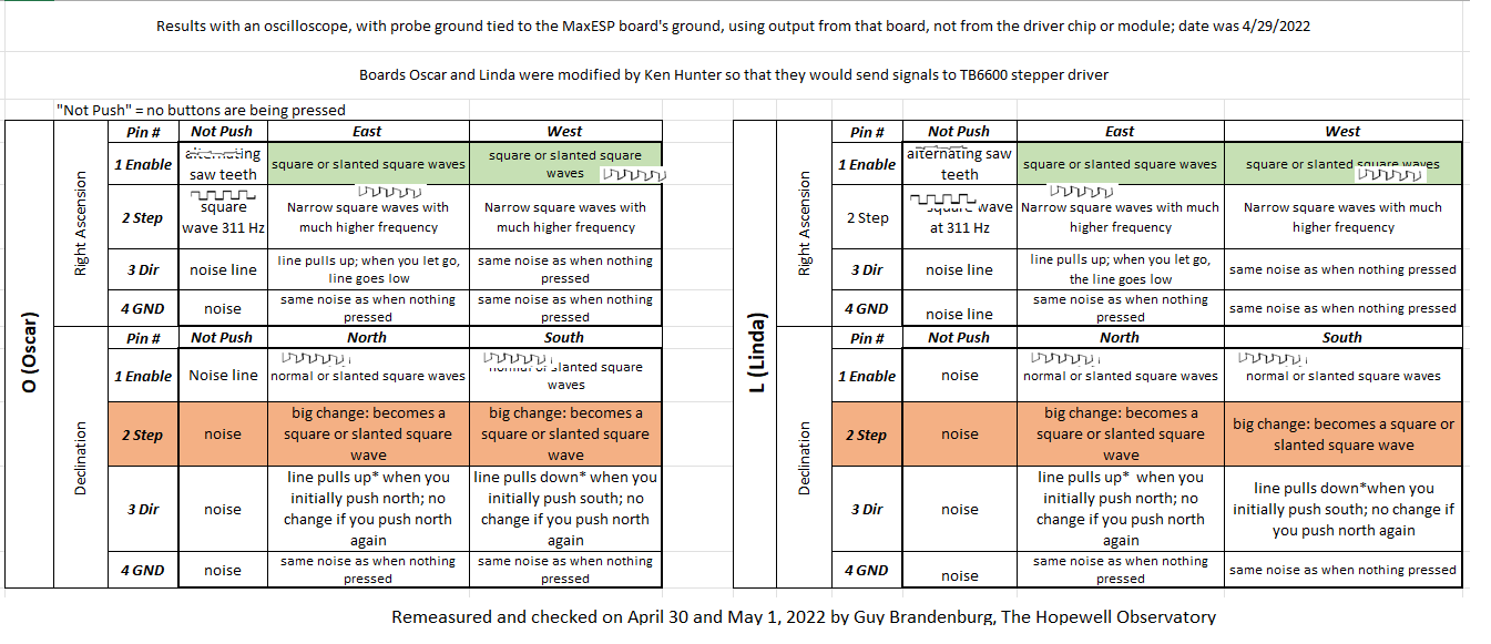
In any case, I attach tables summarizing what I found with the same oscilloscope I had in the previous post. I have highlighted parts that differ between the three boards. Boards “Oscar” and “Linda” are basically identical ones, both of them modified to bypass the location where small, internal stepper motor drivers (about the size of the last joint on your pinky finger) are normally held. Instead, these two boards, both blue in color, connect to two external black-and-green stepper drivers about the size of your hand.
Board “Nancy” differs from the other two in a number of ways: it’s green, which is not important for its function but makes it easier to distinguish. It is also an unmodified one, and it carries TMC5160 stepper driver chips pushed into two rails.
I used orange and green to highlight the differences in output.
With electronics: when it works, it’s amazing, but it is very, very fragile.
==========================
Edit: It all works just fine on my desk. I hope it will also work once we put it into the telescope’s cavities and wire everything up!
I’ve got the new stepper motors, and their drivers, and their power supplies, working away just fine on my desk, and I’m pretty excited and confident that we will have enough power and precision to drive and slew the Ealing properly!
Counter-clockwise from top: Plug strip; Android tablet; OnStep board in black box; 24VDC power supply; weather module; smart hand controller; NEMA23 steppers (2 of them) with connectors on top; two drivers for the steppers; another power supply.
These steppers are very strong: I am completely unable to stop the motors with my hands (bare or gloved) either when they are just tracking or when they are slewing at full speed or guiding at low speed, even with a fairly large fixture on the end of the shaft.
Without Ken Hunter’s expertise, there is no way I could have figured out how to get these particular steppers wired so that they would run, especially since they require those special, large, green and black drivers that you see in the photo above, which are about the size of the palm of your hand. Ken deserves a real round of applause, and more. (I have found that his advice on the OnStep wiki message board is much more accurate and friendlier than the advice of many others there.) In addition, he also repaired two boards that had been incorrectly soldered and assembled by someone else and which I and Alan Tarica purchased from that person, separately.
Before Ken’s intervention, the boards didn’t work. He found a number of assembly and soldering errors, and not only fixed them, but he also ‘flashed’ them with the latest OnStep software versions. At no cost! Now, they work very well.
I want to thank Prasad Agrahar again for his original inspiration and follow-through, and also Alan Tarica for his enthusiastic and knowledgeable assistance and advice (which I don’t always follow).
What’s more, as far as I can tell, this arrangement with super-duper steppers and drivers is unique in OnStep. Something like it clearly exists in some form in the professional or amateur CNC world, which is why we can purchase these insanely complex drivers for less than $9 apiece and the steppers for just $37 each, but to my knowledge nobody in the OnStep world has done this particular arrangement.
The old NEMA-23 steppers and these new ones have the exact same ‘form factor’ except that one can use larger bolts to fasten the new ones to the L-shaped brackets I already have installed.
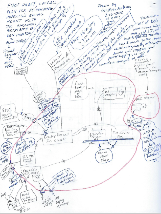
The attached schematic diagram is a first draft of how the connections on the mount itself will be made. The wiring job is going to have a lot of parts, and lots of connections!
At the observatory, we won’t have those old military-grade, 14-connector cables any more, nor that very heavy old hand paddle whose cable we all used to trip over. Instead, I ordered 10 feet of 14-gauge, 4-conductor shielded, stranded cable that is highly rated for both high and low temperatures, in order to connect the DEC drive to the rest of the scope. It will need new strain-relief grommets. So will several other wires. I can re-use most of the existing holes in the cover plates for this mount, and will seal the rest of them to keep out insects. Wiring all of those new connections will take a while!
We will have a local wireless connection (with a small external antenna, like on a router, to make sure there is a good wireless signal), and a small (2x3x5 cm) dedicated basic weather monitor (very basic: just humidity, temp, etc) attached somewhere on the mount*. There will also be an emergency ‘Kill’ switch to allow one to stop the drive immediately if needed.
You can control the scope with a Smart Hand Controller that will be attached via a flexible ethernet-type cable, or, if you prefer, with an inexpensive Android cell phone or tablet that has the proper software installed. (We will leave a tablet up there, with its charging cord.) One won’t need to unclamp, slew, and re-clamp the RA and DEC axes any more in order to acquire a target. We will see how good the pointing accuracy and tracking are, once it’s all up and running.
Since we are using much stronger stepper motors than the ones had been suggested to me and that I had purchased earlier, and they needed a lot more current, we needed different drivers. As a result, most of the connections I had previously fabricated won’t be of much use for us anymore. Perhaps I can give them away to somebody else who is attempting an OnStep conversion on a telescope mount that weighs much less than this one.
Here is a little video of these things in action:
And here is my first draft of the schematics showing how these things all connect inside the scope as well as how we will connect them to the body of the mount itself. It’s crude, but I think it will be useful.
A 3-minute video of the results of our first-time installation of something called an OnStep conversion. We are replacing the telescope drive of a venerable but beautifully machined telescope mount, located at a small group-owned observatory called Hopewell, atop a ridge called Bull Run Mountain*.
It’s alive!
Sorry, it’s not the greatest or clearest video. Also, I mistakenly state at about 0:25 in the video that the right ascension axis was turning at 12 RPM, but it’s not: I should have said 5 RPM, or one revolution in 12 seconds.
You can hear some stuttering of one of the motors. You are right, that is not a good sound. We were able to get it to stop and start making that noise and motion by adjusting the precise positioning of some of the gears. It will take some time and experimentation to get that perfect.
Later on (not captured in this video), when I was trying to slew in the declination axis at the highest speed possible, the stepper motor once again screamed and halted. I’m hopeful that all of those problems can be fixed by doing one or more of these things:
1) adjusting the fit of all those gears;
(2) changing certain parameters of microstepping and current to the stepper motors in software; and/or
(3) increasing the voltage to the board from 18 VDC to 24 VDC.
I’ll need to test things out on my desk at home, using the same OnStep board, but without the gears and timing belt. (That stuff was a royal PITA to remove screw back into place, and none of us have any desire to take them back out again!) I have some identical extra stepper motors that I can test out, with gloved hands, to see if it is possible to stop the motors from turning. Right now, I still don’t think they are putting out the amount of torque needed.
================================
*Yes, that famous Bull Run of Civil War fame is not far away. However, our observatory is named after a different geological feature, namely the Hopewell Gap that cuts through the hard rock of Bull Run Mountain right about where where the creek called Little Bull Run begins.
If you are reading this, you probably know that serious amateur, and all professional, astronomical telescopes (except for Dobs) are generally driven by ‘clock drives’ so that the object one is viewing or photographing stays properly centered as the earth rotates imperceptibly beneath us. The original Ealing motor drive at Hopewell, while turning excellent Ed Byers gears, had been an intermittent problem ever since it was delivered to the University of Marylandabout 50 years ago. It was in fact not operational when they sold it to us for a pittance about 30 years ago. (If you go to the University of Maryland Observatory site I linked to, the scope we have now is the one in the center of the 1970s – era photo labeled ‘Figure 4’.)
Bob Bolster, one of the founding members of Hopewell observatory, disassembled the drive, modified it considerably, and got it working again, several years before I joined the group. The scope worked, off and on, with a very complex clutch system for ‘fast’ and ‘slow’ movement of the scope, for most of the rest of the last 25 or so years, except for occasional motor burnouts and clutch replacements. Also unfortunately, the optics on the original 12″ Ritchey-Chretien telescope, were not very good, so we removed them, had them in an attic for many years, re-tested them, and finally sold the glass and the holders, for a pittance, to someone in Italy who wanted to try to re-figure them.
This was originally a ‘push-to’ telescope, meaning that one loosened up two Byers clutches (one for each axis), located the desired target in the sky, tightened the two clutches, did some fine tuning with an electric hand paddle to center the target more precisely, and then allowed the telescope drive to then keep the object in the center of the eyepiece or camera field of view as long as one wanted. It originally came with metal setting circles (basically, finely-made protractors that showed where the scope is pointing vis-a-vis the polar and declination axes), which made finding targets possible, though not trivial!
About 15 years ago, Bolster (with some help from me) installed Digital Setting Circles, which used a rotary encoder on each axis, along with a small hand-held computer and screen display, to allow one to select a given target; the DSC hand paddle’s display then would indicate how far one should rotate the scope along those axes to find the desired celestial object; when it was in the field of your widest eyepiece, one used the hand paddle to center it more precisely.
Converting this scope to an OnStep drive will, I hope, make this a Go-To scope in which one can command the telescope to aim at whatever target one desires.
Unfortunately, right now, the fastest it seems to rotate in Declination, with no load whatsoever (all scopes have been removed, so no balance or inertia problems) is about one degree per second. So doing a 180-degree turn in a North-South direction would take a full three minutes. A 30-degree turn would take 30 seconds. Can we make this a bit faster? I hope so.
I wasn’t able to really slew in right ascension (East-West) because the counterweight box, even though empty, seems to require too much torque to rotate right now.
Bolster passed away a few years ago, and this summer, the moment I had been dreading finally arrived: the drive on the Ealing died again, and his amazing skills and tenacity in fixing such problems was gone with him. What’s more, in his final years, his incurable, chronic idiopathic neuropathy made it literally impossible for him to speak, and even typing email responses to the rest of us took a very long time. So most of his wealth of knowledge and experience died with him.
As indicated in my earlier posts (here, here, here, and here), with help from others, I was able to take the two motor setups for the two axes out from the mount and get them working again on my workbench in their original format. I was even able to order and install material for the clutches. However, I discovered that one needed to adjust the clutches very, very precisely, or else they wouldn’t work at all.
I couldn’t figure out how to do that.
And nobody else who belongs to our observatory volunteered to help out, except for removing the scopes and drives from their former positions inside the mount.
So I decided to convert to a totally different type of telescope drive, one inspired by the Arduino boards and 3-D printers. A group of really smart and resourceful hobbyists (engineers?) designed a system around the Arduino environment that uses inexpensive off-the-shelf printed circuits and complex sub-boards and components, used originally mostly in the 3-D printers that have become so popular, to drive at telescope just the way astronomers want them to be driven.
Apparently, there have been many, many OnStep successes, but what we are doing may be the largest and most massive mount to date that has done such a conversion.
I was warned that the entire process would take some months. Those warnings were correct. But that’s OK. I’m retired, I have time, and I have access to tools and people who are interested in helping. What’s more, I have learned a whole lot about modern electronics, and my soldering skills are much better than they ever were.
I’d again like to thank Alan Tarica (who’s physically helped a **tremendous** amount), Prasad Agrahar (who first showed me the OnStep conversions he had done on a much smaller equatorial mount), Howard Dutton (who first conceived and implemented OnStep), Ken Hunter (who made and **donated** to us a complete, functional OnStep board together with all sorts of accessories and walked me by phone and video through many of my fumbling first steps), Khalid Bahayeldin, George Cushing, and many others.