• My series on making a Newtonian telescope
  • How Leon Foucault Made Telescopes

Guy's Math & Astro Blog

Guy's Math & Astro Blog

Category Archives: astronomy

Cleaning Up a Century-Old Refractor

18 Sunday Aug 2019

Posted by gfbrandenburg in astronomy, History, Hopewell Observatorry, Optics, Telescope Making

≈ 5 Comments

Tags

antique, Carl Kiess, Hopewell, refractor, Telescope

Last week, I was helping staff and students at the University of Maryland’s Observatory to clean out a storage trailer.

We noticed a seven-foot-long, 6-inch diameter telescope that had been sitting in a corner there, unused, ever since it was donated to the National Capital Astronomers (NCA) club nearly ten years earlier by the son of the original owner, Carl Kiess,  who had worked at the Lick Observatory in California and the National Bureau of Standards in or near DC, but who had passed away nearly fifty years earlier. I figured I could put it on a motorized telescope mount at Hopewell Observatory and at a minimum test the optics to see if they were any good. The current officers and trustees of NCA all said they thought this was a good idea.

One thing that caught my eye was how filthy and flaky the coating was on the tube itself, although the lens appeared to be in good shape.

IMG_5043
IMG_5044

IMG_5027

The drive, while impressive, does not have a motor, requires a pier, and is extremely heavy. I decided not to mess with the drive and to put it temporarily on our existing, venerable, sturdy, motorized, electronic drive we have at Hopewell Observatory.

So I experimented with various abrasives and solvents to clean off the nasty green coating; a fine wire wheel inserted in an electric drill did the best job. Here it is partly cleaned off:

GHCW2253
IMG_5059

I then used Brasso for a final polish, followed by a final cleaning with acetone, and then applied several coats of polyurethane to keep it looking shiny for a number of years. (The lenses stayed covered for all of this!) So this is how it looks now:

IMG_5060
IMG_5061

The next task is to make a temporary holder and then put it on the mount, and then test the optics.

Bath Interferometer at Stellafane

06 Tuesday Aug 2019

Posted by gfbrandenburg in astronomy, flat, monochromatic, optical flat, Optics, Telescope Making

≈ Leave a comment

Tags

Bath interferometry

I am posting some photos and videos of the demonstration of a Bath interferometer on Saturday at the 2019 Stellafane convention.

IMG_4951

IMG_4951

IMG_4952

IMG_4953

IMG_4953

IMG_4955

IMG_4956

IMG_4956

IMG_4957

IMG_4957

IMG_4958IMG_4959

IMG_4960

IMG_4960

IMG_4961IMG_4962

IMG_4963

IMG_4963

IMG_4964

IMG_4964

Silvering Mirrors, and More, at Stellafane

05 Monday Aug 2019

Posted by gfbrandenburg in astronomy, flat, History, Math, monochromatic, optical flat, Optics, science, teaching, Telescope Making, Uncategorized

≈ 3 Comments

For me, these were the two most significant demos at the 2019 Stellafane Convention in Springfield, Vermont:

(1) Silvering large mirrors, no vacuum needed

We had a demonstration by Peter Pekurar on how to apply a layer of Silver (metallic Ag, not aluminum) onto a telescope mirror, accurately, with a protective, non-tarnishing overcoat, that works well. I looked through such a scope; the view was quite good, and I was told that interferograms are great also.

What’s more, the process involves overcoating a mirror with spray bottles of the reagents, without any vacuum apparatus needed at all. Note: Silver coated, not aluminum coated. This is big for me because the upper limit at our club’s aluminizer is 12.5″, but some of us are working on larger mirrors than that; commercial coaters currently charge many hundreds of dollars to coat them.

You can find information on some of these materials at Angel Gilding. Peter P said he will have an article out in not too long. Here are a few photos and videos of the process:

IMG_4972

Finished mirror; notice it’s a little blotchy


IMG_4978

IMG_4978


IMG_4981

IMG_4981

IMG_4985IMG_4987

(2) Demo and links for Bath Interferometer (see http://gr5.org/bath )

How to set up and use a Bath interferometer to produce highly accurate interferograms of any mirror for many orders of magnitude less cash than a Zygo interferometer. As I wrote earlier, Alan Tarica had taken the lead on fabricating one at the CCCC – NCA ATM workshop, and we eventually got it to work, but found it rather frustrating and fiddly to use.

The presenter is a HS teacher, and it shows: he explains things very clearly! On his website ( http://gr5.org/bath ) you can get plans for 3-D printing the parts for the Bath device, if you have any access to a 3-D printer, so you can print the parts out for yourself. He also has links to vendors that are selling parts for it, such as certain small lenses, mirrors and beam splitters. He shows you where you can get them for very little money from Surplus Shed and such places. Or you can purchase his really inexpensive kits that he’s already 3-D printed for you. Plus parts for an XYZ stage, which you will need for fine focus. The whole setup (not counting mirror stand and two tripods, which he assumes you have access to already) is under $130.

I will need to look carefully at our setup as built almost completely by Alan, and see how it differs and what we would need to do to make it better. The problem is that there are lots of little, tiny parts, and many of them need to be adjustable. We saw him doing LOTS of little adjustments!

Before his talk, I had absolutely no idea how this (or similar interformeters) really worked. Now I understand: the interference fringes that we see are really contour lines – like we see on on a USGS topo map, only with the mirror tilted in one direction or the other. A big difference with the USGS topo map is that there, the contour lines (isohypses – a new word for me today) are often 10 feet to 100 meters apart. In interferometry, the contour intervals are either one or one-half lambda (wavelength of light) apart – a really tiny amount! We need that level of accuracy because the surface we are studying is sooooooo flat that no other measuring system can work. His explanation of this whole thing now makes perfect sense to me. And the purpose of the software (free!) is to un-slant the mirror and re-draw it using the countour-line information.

Beautifully clear explanation!

Caution: a friend who works professionally in optics told me his team had made three Bath interferometers, using cheap but good quality ebay xyz stages, and found that they were just too much trouble; so they borrowed a very expensive commercial interferometer (costing many tens of kilobucks) from another department and are using that instead. I’m not selling my house to get a Zygo interferometer!!! But I will try the Bath interferometer instead.


Commercial Sites for Astronomy Viewing Near New Mexico

29 Saturday Jun 2019

Posted by gfbrandenburg in astronomy, education

≈ Leave a comment

Tags

Astronomical observations, Astronomy Inns, commercial providers, dark skies, telescopes

I thought I would share the URLs of a number of commercial establishments that offer astronomical viewing with very dark skies. Most of these are located in or near New Mexico.

http://www.casitasdegila.com/stargazing.html

https://sites.google.com/site/cosmiccampgroundinformation/

https://www.airbnb.com/rooms/7697447

http://www.astronomyadventures.com/

http://skycenter.arizona.edu/

http://www.lowell.edu/ 

http://www.noao.edu/outreach/kpoutreach.html

http://mcdonaldobservatory.org/visitors

https://www.facebook.com/SunglowRanchAZ

http://www.canyonoftheeagles.com/eagle-eye-observatory

http://www.csspdarkskyfund.org/home/stargazing_information  [Cherry Springs PA]

https://lennox-addington.on.ca/explore/dark-sky-viewing-area  [Ontario Canada]

And in Chile: http://www.haciendalosandes.com/en/astronomy.html

Source: Lynn Rice of New Mexico Skies, which now (sadly) only does remote hosting — in other words, people far away use the telescopes at NMS via fast internet connections, for a fee.

New Mexico Skies, Inc.
9 Contentment Crest #182
Mayhill NM 88339


Videos on Telescope Making from Gordon Waite

03 Thursday Jan 2019

Posted by gfbrandenburg in astronomy, astrophysics, flat, optical flat, Optics, Telescope Making

≈ Leave a comment

Tags

figuring, flats, Gordon Waite, machine, optical, Optics, parabolizing, Polishing, Telescope Making, testing optics, Waite Research, youtube

Gordon Waite is a commercial telescope maker who has made a number of very useful YouTube videos on his grinding, polishing, parabolizing, and testing procedures. I thought some of my readers might be interested in viewing them. The link is here, or else you can copy and paste this:

https://www.youtube.com/user/GordonWaite/videos

Some Progress – AT LAST! – With Figuring the 16.5″ f/4.5 Thin Mirror That Headlines This Blog

10 Saturday Nov 2018

Posted by gfbrandenburg in astronomy, Hopewell Observatorry, Optics, Safety, Telescope Making

≈ Leave a comment

Tags

Bob Bolster, George Ritchey, Grinding, Hopewell Observatory, matching Ronchi, Mel Bartels, Polishing, Ronchi, ronchigram, Telescope Making, testing

I have been wrestling with this mirror for YEARS. It’s not been easy at all. The blank is only about twice the diameter of an 8″ mirror, but the project is easily 10 times as hard as doing an 8-incher. (Yes, it’s the one in the photo heading this blog!)

Recently I’ve been trying to figure it using a polishing/grinding machine fabricated by the late Bob Bolster (who modeled his after the machine that George Ritchey invented for the celebrated 60″ mirror at Mount Wilson over a century ago). That’s been a learning exercise, as I had to learn by trial and error what the machine can and cannot do, and what strokes produce what effects. The texts and videos I have seen on figuring such a large mirror with a machine have not really been very helpful, so it’s mostly been trial and error.

My best results right now seem to come from using an 8″ pitch tool on a metal backing, with a 15 pound lead weight, employing long, somewhat-oval strokes approximately tangential to the 50% zone. The edge of the tool goes about 5 cm over the edge of the blank.

This little movie shows the best ronchigrams I have ever produced with this mirror, after nearly 6 hours of near-continuous work and testing. Take a look:

Final movie Nov 9

Final movie Nov 9

And compare that to how it used to look back in September:

hill and anomaly on 16

hill and anomaly on 16


Also compare that to the theoretically perfect computed ronchigrams from Mel Bartels’ website:

perfect theoretical ronchigrams for guy's 42 cm mirror

Part of the reason this mirror has taken so long is that after grinding and polishing by hand some years ago, I finally did a proper check for strain, and discovered that it had some pretty serious strain. I ended up shipping it out to someone in Taos, New Mexico who annealed it – but that changed the figure of the mirror so much that I had to go back to fine grinding (all the way back to 120 or 220 grit, I think), and then re-polishing, all by hand. I tried to do all of that, and figuring of the mirror, at one of the Delmarva Mirror Making Marathons. It was just too much for my back — along with digging drainage ditches at Hopewell Observatory, I ended up in a serious amount of pain and required serious physical therapy (but fortunately, no crutches), so this project went back into storage for a long, long time.

Recently I’ve tried more work by hand and by machine. Unfortunately, when I do work by hand, it seems that almost no matter how carefully I polish, I cause astigmatism (which I am defining as the mirror simply not being a figure of rotation) which I can see at the testing stand as Ronchi lines that are not symmetrical around a horizontal line of reflection. (If a Ronchi grating produces lines that look a bit line the capital letters N, S, o Z, you have astigmatism quite badly. If astigmatism is there, those dreaded curves show up best when your grating is very close to the center of curvature (or center of confusion) of the central zone.

Using this machine means controlling or guessing at a LOT of variables:

  1. length of the first crank;
  2. length (positive or negative) of the second crank;
  3. position of the slide;
  4. diameter of the pitch lap;
  5. composition of the pitch;
  6. shape into which the pitch lap has been carved;
  7. amount of time that the lap was pressed against the lap;
  8. whether that was a hot press or a warm press or a cold press;
  9. amount of weight pushing down on the lap;
  10. type of polishing agent being used;
  11. thickness or dilution of polishing agent;
  12. temperature and humidity of the room;
  13. whether the settings are all kept the same or are allowed to blend into one another (eg by moving the slide);
  14. time spent on any one setup with the previous eleven or more variables;

Here is a sketch of how this works

bolster's ritchey-like machine

Difficulties in Using the Matching Ronchi Test on a 12″ Cassegrain Mirror

08 Saturday Sep 2018

Posted by gfbrandenburg in astronomy, flat, Hopewell Observatorry, optical flat, Optics, Telescope Making

≈ 2 Comments

Tags

Astro Bananas, cassegrain, couder, double pass auto collimation, ealing, foucault, Hopewell Observatory, matching Ronchi, Mel Bartels, Ronchi, ronchigram

The other regulars and I at the DC ATM group at the CCCC have been trying to test a 12 inch Cassegrain mirror and telescope manufactured nearly 50 years ago by a company called Ealing and currently owned by the Hopewell Observatory, of which I am a member. It hasn’t been easy. I discussed this earlier on Cloudy Nights.

Reports from several people, including Gary Hand and the late Bob Bolster, indicated that the optics on this mirror weren’t good at all. Apparently the folks at the University of Maryland’s observatory were sufficiently unhappy with it that they either sold it or gave it to National Capital Astronomers, a local astronomy club, who in turn gave it or sold it to Hopewell Observatory.

With a plain-vanilla Ronchi test, we could see that the mirror was very smooth and continuous, with no turned edge, astigmatism, or bad zones. With the Foucault/Couder zonal test (aka “Foucault” test) , I got results indicating that it was seriously overcorrected: some sort of hyperboloid, rather than the standard paraboloid characteristic of classical Cassegrain telescopes, which have a parabolic primary mirror and a hyperbolic secondary mirror.

However, I have begun losing my faith in my zonal readings, because they often seem to give results that are way out of whack compared to other testing methods.

So we decided to do some additional tests: the Double-Pass Auto-Collimation (DPACT) test used by Dick Parker, as well as the Matching Ronchi test (MRT).

The DPACT is very fiddly and exacting in its setup. We used (and modified) the setup lent to us by Jim Crowley and illustrated by him at his Astro Bananas website. Our results seem to show that the mirror is in fact NOT parabolic, rather, overcorrected, which confirms my Foucault measurements. If it were a perfect paraboloid, then the ronchi lines would be perfectly straight, but they definitely are NOT: they curve one way when inside the focal point, and curve the other when the tester is outside the focal point.

We also tested the entire setup on a radio tower that was about half a mile (~1km) distant. We found that the images were somewhat blurry no matter what we did.

We also attempted the MRT on the same mirror. However, requires very accurate photography and cutting-and-pasting skills in some sort of graphics programs. What you are inspecting is the curvature of the Ronchi lines. Here is the result that Alan T and I got last night:

matching ronchi for 12 inch cass

In black is the ideal ronchigram for this mirror, according to Mel Bartels’ website. The colored picture is the one we made with either my cell phone or the device I finished making earlier this week, shown in my previous post. Here are the two images, separated rather than superimposed:

IMG_1337

ideal ronchigram 12 inch cass ealing

The mirror’s focal length is 47.5″ and the grating has 100 lines per inch, shown somewhat outside of the radius of curvature. The little ‘eyelash’ on the lower left is simply a stray wire that was in the way, and doesn’t affect the image at all. The big hole in the middle is there because the mirror is a cassegrain.

I don’t know about you, but I don’t really see any differences between the real mirror and the theoretical mirror. Do you?

Conclusion

So, what does this all mean?

  • One possibility is that the mirror is in fact perfectly parabolic (as apparently shown by the MRT, but contrary to what I found with Foucault and DPACT) but there is something wrong with the convex, hyperbolic secondary.
  • Another possibility is that the mirror is in fact NOT parabolic, but hyperbolic, as shown by both my Foucault measurements and the DPACT (and contrary to the MRT), which would mean that this telescope was in fact closer to a Ritchey-Chretien; however, since it was marketed as a classical Cassegrain, then the (supposedly) hyperbolic secondary was in fact not tuned correctly to the primary.
  • The answer is left as an exercise for the reader.
  • A star test would be the best answer, but that would require being able to see a star. That hasn’t happened in these parts for quite some time. In addition, it would require an eyepiece holder and a mount of some sort. Or else setting up an indoor star…

Latest Ronchi or Knife-Edge Tester for Mirrors and Other Optics Using a WebCam

07 Friday Sep 2018

Posted by gfbrandenburg in astronomy, Optics, science, Telescope Making

≈ 1 Comment

Tags

brightness, color balance, exposure, focus, foucault, gain, knife edge, Ronchi, testing, webcam

Here is the latest incarnation of my webcam Ronchi and knife edge (or Foucault) tester. It’s taken quite a few iterations to get here, including removing all the unnecessary parts of the webcam. I attach a still photo and a short video. The setup does quite a nice job of allowing everybody to see what is happening. The only problem is setting the gain, focus, exposure, brightness, color balance, contrast, and so on in such a way that what you see on the screen resembles in any way what your eye can see quite easily.

IMG_1335

IMG_1336

IMG_1336

Observe the Stars at Lake Artemisia Natural Area, September 30

30 Thursday Aug 2018

Posted by gfbrandenburg in astronomy, nature, Uncategorized

≈ Leave a comment

Tags

Berwyn Heights, Lake Artemisia, observing, Public

On September 30, members of the public will have the opportunity to observe several planets, the moon, and other heavenly objects through some telescopes to be provided by local amateur astronomers, including members of NCA and NOVAC, at the lovely Lake Artemisia Natural Area in Berwyn Heights, MD.

The location has a wide open southern horizon over the lake, and is surprisingly well-shielded from lights from local highways and shopping centers. The address is

Lake Artemesia Natural Area, Berwyn Road and 55th Avenue, Berwyn Heights, MD 20740

Park Contact numbers are: 301-627-7755  or TTY: 301-699-2544

Normally this park closes at sunset, but it will remain open for this event, which is scheduled for 7:00 (just about sunset) to 11:00 pm (just after moonrise) on Sunday evening, September 30. The event is free. I’ve attached a couple of maps. Please note that Berwyn Road dead-ends at the Metro rail lines.


Lake Artemisia best
lake artemesia 2

We should be able to see Venus, Jupiter, Saturn, Mars, and the rising Moon, if weather permits. Volunteers with telescopes would be appreciated!

Quantifying Progress in the Fight Against Turned Down Edge

27 Tuesday Mar 2018

Posted by gfbrandenburg in astronomy, Math, Optics, Telescope Making, Uncategorized

≈ Leave a comment

Tags

Applebaum, Mel Bartels, Ronchi

By Guy Brandenburg

3/27/2017

I describe here an attempt to quantify progress (or lack thereof) in the removal of the classic, and dreaded, turned-down edge (TDE) present on a 16.5” Newtonian glass mirror blank that I have been trying to “figure” for some years.  The figuring process means changing a piece of glass that approximates a small section sliced out of a large hollow sphere, into a highly-accurate paraboloid — with the required level of accuracy being measured in nanometers.


Many amateur and professional telescope makers have maintained that you can only fix figuring errors if you can measure them. Not being able to get good, repeatable measurements of the TDE on my mirror, I had been sort of floundering, failing to get rid of the TDE even after YEARS of work (off and on; mostly off). So a decision was made to try to quantify things.


We recently had some success in matching computer-generated Ronchi images of theoretically-perfect mirrors with photos taken of works in progress, simply by cutting and pasting – which has been recommended by Mel Bartels in particular for quite some time. For the first time, I got the hang of it, and we were able to help a first-timer (Mike L) to figure a 10” plate glass f/5.4 mirror only ¾” thick to just about exactly ¼ lambda, according to our combined, repeated, careful measurements on a mirror that was cooled both by immersion in a room-temperature water bath and by sitting in a closet in the very same testing room for an entire weekend.


Prior to this experiment, I had been taking short videos of the entire mirror, moving the ronchi grating back and forth across the center of curvature. These videos reveal and record a lot of qualitative information about the mirror, including vocal commentary, but I found it impossible to transfer the images to my laptop for closer analysis until I got home, across town, which meant that the turn-around time after testing a mirror was much too long to be of any use. I had tried quite a large number of various strokes suggested by others, by our reading various ATM manuals, and by just thinking; but the very serious TDE on this (for me, relatively ambitious) project never seemed to get any better.


I simply gave up on imaging via video clips, since they were too hard to manipulate or measure on my phone, and which required too much bandwidth to send to my laptop until I got home. This time, I took Ronchi still-images on my cell phone, between 0.2 and 0.5 inches outside of the center of curvature.

guys 16 perfect

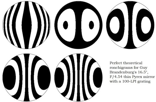
(My experience has been generally easier to discern defects in a Ronchigram when the lines curve outwards at the top and bottom, which would mean the test grating is  OUTSIDE the COC of a partly-parabolized mirror, as you see on the left in the black-and-white image above. However, when the lines curve inwards at the top and bottom, like the images in the center and to the right, then many serious defects remain hidden.
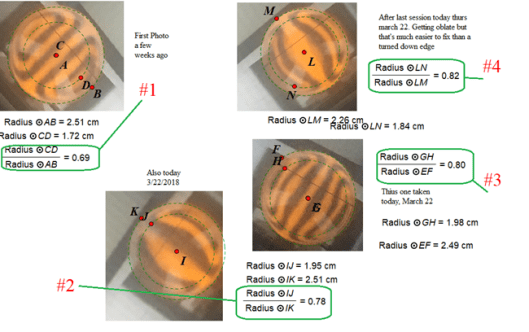
 quantify TDE

Procedure:

A standard 100 LPI grating from Willmann-Bell and a yellow LED were used, on an XYZ stage partly fabricated by me and placed exactly twice the focal length from the primary. Images were taken with an iPhone 6, shooting images zoomed in as much as possible. An attempt was made to have matching ronchigrams, i.e., with the same number of vertical lines showing.


(This was a weak point of the experiment. For one, it’s hard to hold cell phone steady enough, and an observer will notice that the images do NOT have exactly the same number of lines. That’s because I did not have a printout of the previous image right in front of me to make comparisons to. All that needs to be fixed in subsequent iterations. Also, other imaging devices need to be tried, as well.)


I was in fact able to email individual photograph frames to my laptop at the lab. After downloading the clearest images to my laptop, I used plain old MS Windows Paint to shrink and crop the useful portion of the picture, and then pasted the result into a Geometry software (Geometer.s Sketchpad, or GSP) that I was already familiar with. GSP was then used to draw a circle around the circumference of the image of the nearly-perfectly-circular glass disk, adjusting this as well as possible. This process automatically generated the center of the disk. Using that center, a second, and smaller, circle was drawn whose circumference was placed at the location along the ronchi lines where they appeared to begin to turn outwards. GSP was then  to measure directly the radii of the two circles and to compute their ratio.


A final ratio of 0.7, just to pick a number that is easy to compute, means that just about half of the area of the mirror is covered by a wide rolled-down edge, since the ratio of areas is equal to the square of the ratio of the respective radii, and 0.7 squared is 0.49, or 49%.


In the diagram above, the images go in chronological order but COUNTER-clockwise, from upper left (labeled #1), which was made in mid- or early March, through the next three images, all taken on March 22. In between each image, various strokes were employed in figuring sessions for anywhere between 15-20 minutes to attempt to fix the TDE. All the figuring sessions involved sub-diameter laps anywhere from 8 to 12 inches in diameter that had been warm-pressed upon the mirror. The strokes were both forward and back and incorporated enough of a ‘W’ stroke to cover the entire mirror, using cerium oxide on either tempered burgundy or Acculap pitch, depending. The edge of the tool was allowed to go up to the edge of the mirror, +/- maybe 5 mm. The goal was simply to wear down the glass in the center until it caught up with the amount that the edge had been worn down. None of the laps seemed to have full contact with the mirror out to the very edge; thus the end of the stroke was NOT at the edge of the mirror.


You will notice that these ratios, circled in green, seem to increase monotonically from 69% to 80%, which is gratifying: if this real, then the fraction of the mirror that is NOT covered by TDE has gone from about 47% to about 67%, as you can see here. (Note: in figure #1, the large circle was denoted circle AB, and the smaller circle was denoted circle CD. I know that points A and C are not identical, but they are rather close; that error will be fixed in subsequent iterations.)

However: the key question is: IS THIS REAL? Or am I merely fooling myself?

I don’t know yet.

I certainly hope it is real.

But it needs to be checked with subsequent investigation.

My attempt at limiting my own subjectivity or wishful thinking was to try to draw the circles at the place where the more-or-less vertical lines began turning outwards. Hopefully that location really corresponded to the place where the turned/rolled edge began. However, it is entirely possible that the precise apparent location of the beginning of the TDE very much depends on exactly how many lines appear in the Ronchigram, thus, precisely how far from the COC the grating is located.

Unfortunately, often times I have to dismantle the entire apparatus, because we have to close up shop for the night, or somebody else needs to use the tester on another mirror. Thus, it is nearly impossible to ensure that the measurement apparatus remains undisturbed.

My next steps, I think, are these:

  1. Have a separate, and very simple ronchi apparatus that just consists of a grating and a light.
  2. Have previous images right in front of me as I prepare to take the next Ronchigrams, so that I can match the number of lines visible.
  3. Perhaps I should take a series of said standardized ronchigrams both inside and outside of COC with, say, 5 lines visible. I should also take some ronchigrams that might accentuate and expose any possible astigmatism; that is, very close to the COC. Any Ronchi lines that resemble the letters S, Z, J, U, or N would be very bad news.
  4. Attempt to attach a cheap video camera with built-in LED, Ronchi grating, and a suitable lens to make steadier images free from hand wobbles.

I would like to thank Isaac and Elias Applebaum for their diligent and noted explorations in solving a similar question relating to fixing or preventing TDE. That STEM project won them a number of well-deserved awards.


← Older posts
Newer posts →

Subscribe

  • Entries (RSS)
  • Comments (RSS)

Archives

  • February 2026
  • December 2025
  • November 2025
  • October 2025
  • September 2025
  • July 2025
  • January 2025
  • November 2024
  • October 2024
  • August 2024
  • July 2024
  • May 2024
  • April 2024
  • January 2024
  • December 2023
  • October 2023
  • August 2023
  • June 2023
  • May 2023
  • April 2023
  • November 2022
  • October 2022
  • August 2022
  • July 2022
  • June 2022
  • May 2022
  • April 2022
  • February 2022
  • January 2022
  • December 2021
  • October 2021
  • September 2021
  • August 2021
  • July 2021
  • June 2021
  • May 2021
  • March 2021
  • December 2020
  • October 2020
  • September 2020
  • August 2020
  • March 2020
  • February 2020
  • January 2020
  • December 2019
  • November 2019
  • September 2019
  • August 2019
  • June 2019
  • May 2019
  • January 2019
  • November 2018
  • October 2018
  • September 2018
  • August 2018
  • May 2018
  • March 2018
  • January 2018
  • November 2017
  • October 2017
  • September 2017
  • August 2017
  • July 2017
  • June 2017
  • May 2017
  • April 2017
  • February 2017
  • December 2016
  • September 2016
  • June 2016
  • May 2016
  • April 2016
  • March 2016
  • February 2016
  • January 2016
  • December 2015
  • November 2015
  • August 2015
  • July 2015
  • April 2015
  • March 2015
  • February 2015
  • January 2015
  • December 2014

Categories

  • astronomy
  • astrophysics
  • education
  • flat
  • History
  • Hopewell Observatorry
  • Math
  • monochromatic
  • nature
  • optical flat
  • Optics
  • Safety
  • science
  • teaching
  • Telescope Making
  • Uncategorized

Meta

  • Create account
  • Log in

Blog at WordPress.com.

  • Subscribe Subscribed
    • Guy's Math & Astro Blog
    • Join 54 other subscribers
    • Already have a WordPress.com account? Log in now.
    • Guy's Math & Astro Blog
    • Subscribe Subscribed
    • Sign up
    • Log in
    • Report this content
    • View site in Reader
    • Manage subscriptions
    • Collapse this bar
 

Loading Comments...