Alan Tarica, Pratik Tambe, Tom Crone and I have been pulling our hair out for a couple of years, trying to use cameras and software to measure the ‘figure’ of the telescope mirrors that we and others produce in our telescope-making class.
There has been progress, and there has been frustration.
I think we finally succeeded!
Some of the difficulties have been described in previous posts. In brief, we want our mirrors to be really, really close to a perfect paraboloid. There are many ways of doing those measurements and seeing whether one is close enough, but none of those methods are easy!
(By the way, one needs the entire mirror to be within one-tenth of a wave-length of green light of that ideal paraboloid! That’s extremely tiny, and equivalent to the thickness of a pencil over a ten-mile diameter!)
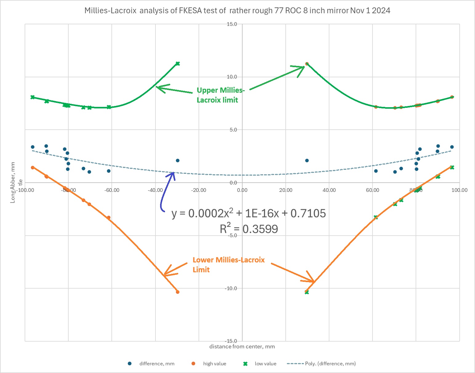
I think I can finally report a victory. My evidence is this graph that I made just now, using data that Alan and I gathered last night with our setup, which consists of a surveillance camera coupled to an old 35mm SLR film camera lens, which is mounted on a linear actuator screw connected to a stepper motor controlled by an Arduino and a Python app developed by Pratik.
Something seemed to be always a bit — or a lot — ‘off’.
The blue dots just above the x-axis are the measurements for this one particular mirror with a diameter of 8″ and a radius of curvature of 77 inches.
The dotted blue curve in the middle of the image is the best-fit parabola for those dots. Notice that the R-squared value (variance) for that curve is not great: 0.3599.
But that variance isn’t important. What is important is the green and orange blobs and curves above and below the blue ones.
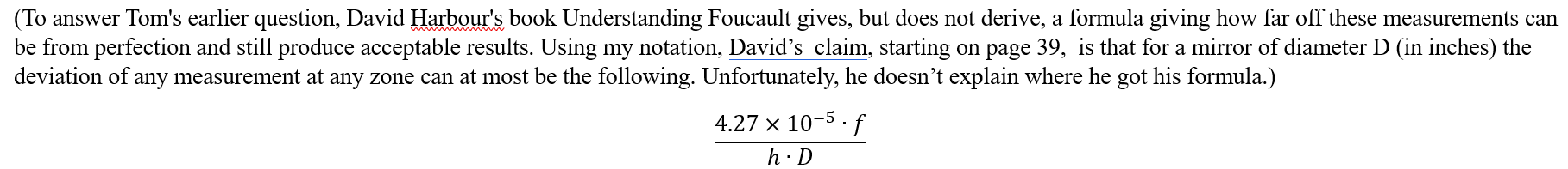
The green and orange curves are the upper and lower allowable limits for the measurements of this particular mirror, using the
Clearly, the blue dots are all well within the green and orange curves.
Which means that this mirror is sufficiently parabolized.
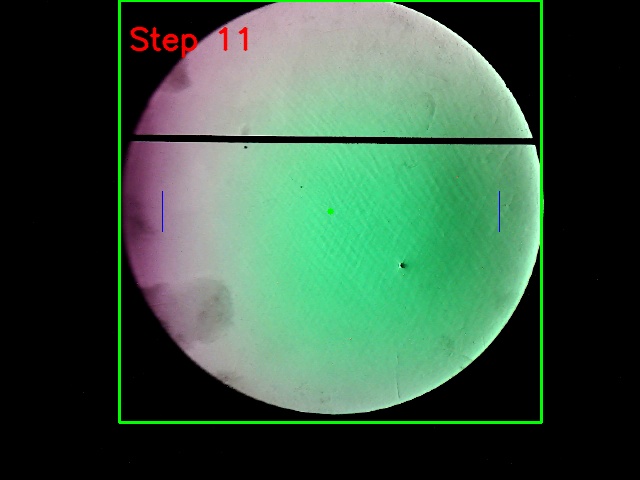
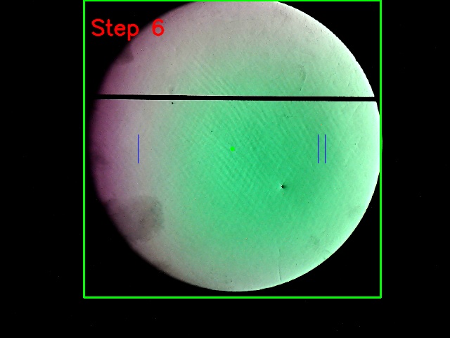
The fact that the blue dots don’t fit the dotted line perfectly, and behave pretty oddly at positive or negative 80 millimeters, both agree with the fact that we can see on the photos that the surface of this mirror is rather rough, as you can see in the images below. Note also that the image labeled ‘Step 6’ found not one, but two null zones on the right, indicated by two vertical blue lines.
So, finally, we have an algorithm that gives good measurements! What I still want to do is to automate all the spreadsheet calculations that I just did today. Perhaps we can upload them to something like FigureXP by Dave Rowe and James Lerch.
Thanks very much to all those who have helped, whom I should look up and name here.
Caveat: This method can give really ridiculous measurements close to the center and close to the edge.
PS: if anybody wants the raw data, just email me at gfbrandenburg at gmail dot com.
For many years now, I have been trying and (mostly) failing at using some sort of digital camera when testing the optics of the mirrors we fabricate and evaluate at the ATM workshop at the Chevy Chase Community Center here in DC.
I can now report that there finally is some useful and non-vignetted light at the end of the testing tunnel!
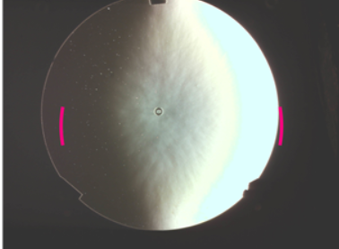
Foucault, knife-edge image, raw
Same mirror, at a different longitudinal location, image flipped right to left (ie across the y-axis), and then pasted onto the original image
Same mirror, same location as the image directly above, with circles and measurements added in Geometer’s Sketchpad
I used an old Canon FD film camera lens (FL=28 mm) that I got about 40 years ago and haven’t used in several decades to get a bunch of really nice knife-edge images of a 16″ Meade mirror, located on a stage that can be moved forward and back in whatever steps I like by a smartphone app and a stepper motor setup that Alan Tarica and Pratik Tambe designed and put together.
Just now, I finally figured out how to use IrfanView to take one of the images, flip it left-to-right (that is, across the y-axis) and superimpose one onto the other with 50% transparency. A bright ring appeared, which shows the circular ring or zone where the light from our LED, located just under the camera lens, goes out to the mirror and bounces directly back to the lens and is captured by the sensor as a bright ring.
I then captured and pasted that image into Geometer’s Sketchpad, which I used to draw and measure the radii of two circles, centered at the doughnut marking the center of the mirror. This is a somewhat crude measurement of the radii, but it appears that this zone is is at 83% of the diameter (or radius) of the original disk, which is 16 inches across.
Now I just need to do the same thing for all of the other images, and then correlate the radii of the bright zones with the longitudinal (z-axis) motion of the camera and stand, and I will know how close this mirror is to a perfect paraboloid.
There is an app that supposedly does this for you, called Foucault Unmasked, but it doesn’t seem to work well at all. As you can see from these images, FU is unable to find zones that are symmetrically placed on either side of the center of the mirror. I don’t know what algorithm FU uses, but it sure is f***ed up.
Foucault Unmasked thinks that those two red marks are the zone being measured here. It’s pretty hard to be more wrong than that.
Again, FU at work, badly. Not quite as awful as the previous one, but still quite useless!
Thanks a lot to Tom Crone, Gert Gottschalk, Pratik Tambe, Alan Tarica, and Alin Tolea for their help and suggestions!
Several people have helped me with this applied geometry problem, but the person who actually took the time to check my steps and point out my error was an amazing 7th grade math student I know.
It involves optical testing for the making of telescope mirrors, which is something I find fascinating, as you may have guessed. Towards the end of this very long post, you can see the corrections, if you like.
Optics themselves are amazingly mysterious. Is light a wave, or a particle, or both? Why can nothing go faster than light? We forget that humans have only very recently discovered and made use of the vast majority of the electromagnetic spectrum that is invisible to our eyes.
But enough on that. At the telescope-making workshop here in DC, I want folks to be able to make the best ordinary, parabolized, and coated mirrors possible with the least amount of hassle possible and at the lowest possible cost. Purchasing high-precision, very expensive commercial interferometers to measure the surface of the mirror is out of the question, but it turns out that very inexpensive methods have been developed for doing that – at least on Newtonian telescopes.
Tom Crone, a friend of mine who is also a fellow amateur astronomer and telescope maker, wondered how on earth we can report mirror profiles as being within a few tens of nanometers of a perfect paraboloid with such simple devices as a classic Foucault knife-edge test.
He told me his computations suggested to him that the best we could do is get it to within a few tenths of a millimeter at best, which is four orders of magnitude less precise!
I assured him that there was something in the Foucault test which produced this ten-thousand-fold increase in accuracy, but allowed that I had never tried to do the complete calculation myself. I do not recall the exact words of our several short conversations on this, but I felt that I needed to accept this as a challenge.
When I did the calculations which follow, I found, to my surprise, that one of the formulas I had been taught and had read about in many telescope-making manuals, was actually not exact, and that the one I had been told was inherently less accurate, was, in fact, perfectly correct! Alan Tarica sent me an article from 1902supposedly explaining the derivation of a nice Foucault formula, but the author skipped a few bunch of important steps, and I don’t get anything like his results. it took me a lot of work, and help from this rising 8th grader, to find and fix my algebra errors. I now agree with the results of the author , T.H.Hussey.
I am embarrassed glad to say that even after several weeks of pretty hard work, an exact, correct formula for one of the commonly used methods for measuring ‘longitudinal aberration’ still eludes me. was pointed out to me by a student who took the time to Let’s see if anybody can follow my work and helped me out on the second method.
But first, a little background information.
Isaac Newton and Leon Foucault were right: a parabolic mirror is the easiest and cheapest way to make a high-quality telescope.
If you build or buy a Newtonian scope, especially on an easy-to-build Dobsonian mount, you will get the most high-quality photons for the money and effort spent, if you compare this type with any other type of optics at the same diameter. (Optical designs like 8-inch triplet apochromats or Ritchey-Chrétiens, or Maksutovs, or modern Schmidt-Cassegrains can cost many thousands of dollars, versus a few hundred at most for a decent 8″ diameter Newtonian).
With a Newtonian, you don’t need special types of optical glass whose indices of refraction and dispersion, and even chemical composition, must be known to many decimal places. The glass can even have bubbles and striations, or not even be transparent at all! Any telescope that only has mirrors, like a Newtonian, will have no chromatic aberration (ie, you don’t see rainbows around bright stars) because there is no refraction – except for inside your eyepieces and in your eyeball. All wavelengths of light reflect exactly the same –but they bend (refract) through glass or other materials at different angles depending on the wavelength.
Another advantage for Newtonians: you don’t need to grind and polish the radii of curvature of your two or three pieces of exotic glass to exceedingly strict tolerances. As long as you end up with a nice parabolic figure, it really doesn’t matter if your focal length ends up being a few centimeters or inches longer or shorter than you had originally planned. Also: there is only one curved mirror surface and one flat one, so you don’t need to make certain that the four or more optical axes of your mirrors and/or lenses are all perfectly parallel and perfectly concentric. Good collimation of the primary and secondary mirrors to the eyepiece helps with any scope, but it’s not nearly as critical in a Newtonian, and getting them to line up if they get knocked out of whack is also much easier to perform.
With a Newtonian, you only need to get one surface correct. That surface needs to be a paraboloid, not a section of a sphere. (Some telescopes require elliptical surfaces, or hyperbolic or spherical ones, or even more exotic geometries. A perfect sphere is the easiest surface to make, by the way.)
In the 1850’s, Leon Foucault showed how to ‘figure’ a curved piece of glass into a sufficiently perfect paraboloid and then to cover it with a thin, removable layer of extremely reflective silver. The methods that telescope makers use today to make sure that the surface is indeed a paraboloid are variations and improvements on Foucault’s methods, which you can read for yourself in my translation.
Jim Crowley performing a Foucault test
It turns out that the parabolic shape does need to be very, very accurate. In fact, over the entire surface of the mirror, other than scratches and particles of dust, there should be no areas that differ from each other and from the prescribed geometric shape by more than about one-tenth of a wavelength of green light (which I will call lambda for short), because otherwise, instead of a sharp image, you just receive a blur, because the high points on the sine waves of the light coming to you would tend to get canceled out by the low points.
Huh?
Let me try to explain. In my illustrations below, I draw two sine waves (one red, one green) that have the same exact frequency and wavelength (namely, two times pi) and the same amplitude, namely 3. They are almost perfectly in phase. Their sum is the dark blue wave. In diagram A, notice that the dark blue wave has an amplitude of six – twice as much as either the red or green sine wave. This means the blue and green waves added constructively.
Next, in diagram B, I draw the red and green waves being out of phase by one-tenth of a wave (0.10 lambda) , and then in diagram C they are ‘off’ by ¼ of a wave (0.25 lambda). You will notice that in the diagrams B and C, the dark blue wave (the sum of the other two) isn’t as tall as it was in diagram A, but it’s still taller than either the red or green one.
One-quarter wave ‘off’ is considered the maximum amount of offset allowed. Here is what happens if the amount of offset gets larger than 1/4:
In diagram D, the red and green curves differ by 1/3 of a wave (~0.33 lambda), and you notice that the blue wave (which is the sum of the other two) is exactly as tall as the red and green waves, which is not good.
Diagram E shows what happens is what happens when the waves are 2/5 (0.40 lambda) out of phase – the blue curve, the sum of the other two, now has a smaller amplitude than its components!
And finally, if the two curves differ by ½ of a wave (0.5 lambda) as in diagram F, then the green and red sine curves cancel out completely – the dark blue curve has become the x-axis, which means that you would only see a blur instead of a star or a planet. This is known as destructive interference, and it’s not what you want in your telescope!
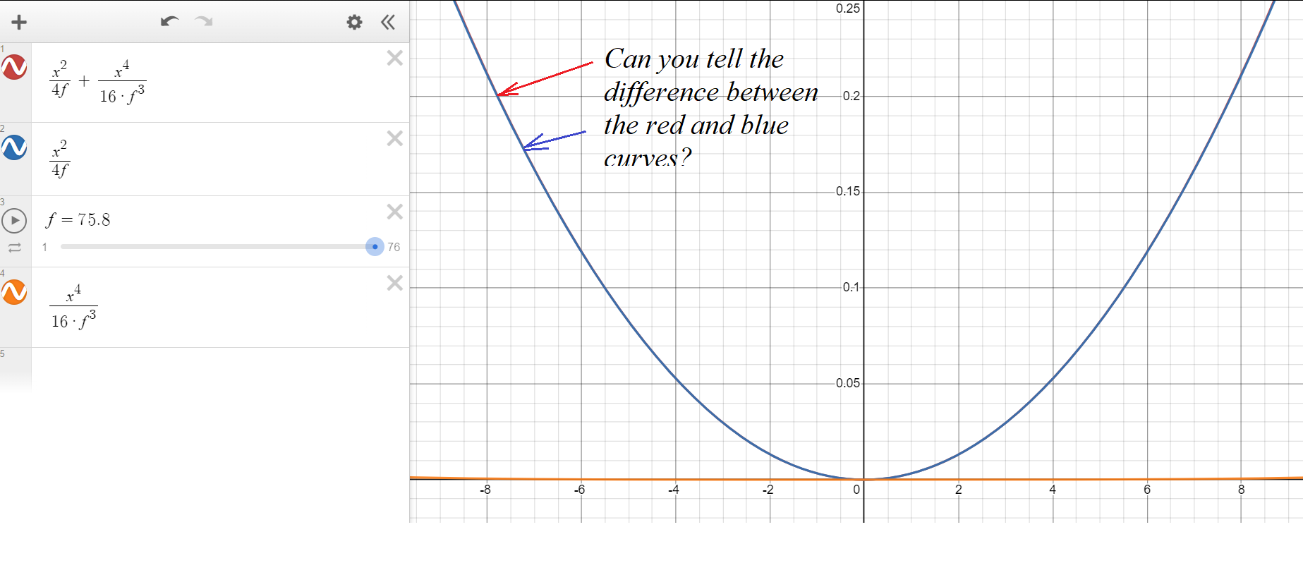
But how on earth do we achieve such accuracy — one-tenth of the wavelength of visible light (λ/10) over an entire surface? And if we do, what does it mean, physically? And why one-tenth λ on the surface of the mirror, when ¼ λ looked pretty decent? For that last question, the reason is that when light bounces off a mirror, any deviations are multiplied by 2. So lambda – about 55 nanometers or 5.5×10^(-8) m- is the maximum allowable depth or height of a bump or a hollow across the entire width of the mirror. That’s really small! How small? Really insanely small.
Let’s try to visualize this by enlarging the mirror. At our mirror shop, we generally help folks work on mirrors whose diameters are anywhere from 11 cm (4 ¼ inches) to 45 cm (18 inches) across. Suppose we could magically enlarge an 8” (20 cm) mirror and blow it up so that it has the same diameter as the original 10-mile (16 km) square surveyed in 1790 by the Ellicott brothers and Benjamin Banneker for the 1790 Federal City. (If you didn’t know, the part on the eastern bank of the Potomac became the District of Columbia, and the part on the western bank was given back to Virginia back in 1847. That explains why Washington DC is no longer shaped like a nice rhombus/diamond/square.)
So imagine a whole lot of earth-moving equipment making a large parabolic dish where DC used to be, a bit like the Arecibo radio telescope, but about 50 times the diameter, and with a parabolic shape, unlike the spherical one that Arecibo was built with.
(Technical detail: since Arecibo was so big, there was no way to physically steer it around at desired targets in the sky. Since they couldn’t steer it, then a parabolic mirror would be useless except for directly overhead. However, a spherical mirror does NOT have a single focal point. So the scope has a movable antenna (or ‘horn’) which can move around to a variety of more-or-less focal points, which enabled them to aim the whole device a bit off to the side, so they can ‘track’ an object for about 40 minutes, which means that it can aim at targets around 5 degrees in any direction from directly overhead, but the resolution was probably not as good as it would have been if it had a fully steerable, parabolic dish. See the following diagrams comparing focal locations for spherical mirrors vs parabolic mirrors. Note that the spherical mirror has a wide range of focal locations, but the parabolic mirror has exactly one focal point.)
I’ll use the metric system because the math is easier. In enlarging a 20 cm (or 0.20 m) mirror all the way to 16 km (which is 16 000 m), one is multiplying 80,000. So if we take the 5.5×10⁻⁸ m accuracy and multiply it by eighty thousand you get 44 x 10-4 m, which means 4.4 millimeters. So, if our imaginary, ginormous 16-kilometer-wide dish was as accurate, to scale, as any ordinary home-made or commercial Newtonian mirror, then none of the bumps or valleys would be more than 4.4 millimeters too deep or too high. For comparison, an ordinary pencil is about 6.8 millimeters thick.
Wow!
So that’s the claim, but now let’s verify this mathematically.
I claim that such a 3-dimensional paraboloid, like the radio dish in the picture below, can be represented by the equation
where f represents the focal length. (For simplicity, I have put the vertex of the paraboloid at the origin, which I have called A. I have decided to make the x-axis (green, pointing to our right) be the optical and geometric axis of the mirror. The positive z-axis (also green) is pointed towards our lower left, and the y-axis (again, green) is the vertical one. The focal point is somewhere on the x-axis, near the detector; let’s pretend it’s at the red dot that I labeled as Focus.)
You may be wondering where that immediately previous formula came from. Here is an explanation:
Let us define a paraboloid as the set (or locus) of all points in 3-D space that are equidistant from a given plane and a given focal point, whose coordinates I will arbitrarily call (f, 0, 0). (When deciding on a mirror or radio dish or reflector on a searchlight, you can make the focal length anything you want.)
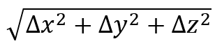
To make it simple, the plane in question will be on the opposite side of the origin; its equation is x = -f. We will pick some random point G anywhere on the surface of the parabolic dish antenna and call its coordinates (x, y, z). We will see what equation these conditions create. We then drop a perpendicular from G towards the plane with equation x = -f. Where this perpendicular hits the plane, we will call point H, whose coordinates are (-f, y, z). We need for distance GH (from the point to the plane) to equal distance from G to the Focus. Distance GH is easy: it’s just f + x. To find distance between G and Focus, I will use the 3-D distance formula:
Which, after substituting, becomes
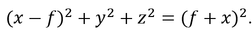
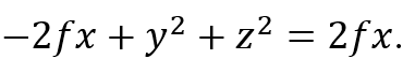
To get rid of the radical sign, I will equate those two quantities, because FG = GH, omit the zeroes, and square both sides. I then get
Multiplying out both sides, we get
Canceling equal stuff on both sides, I get
Adding 2fx to both sides, and dividing both sides by 4f, I then get
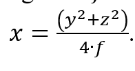
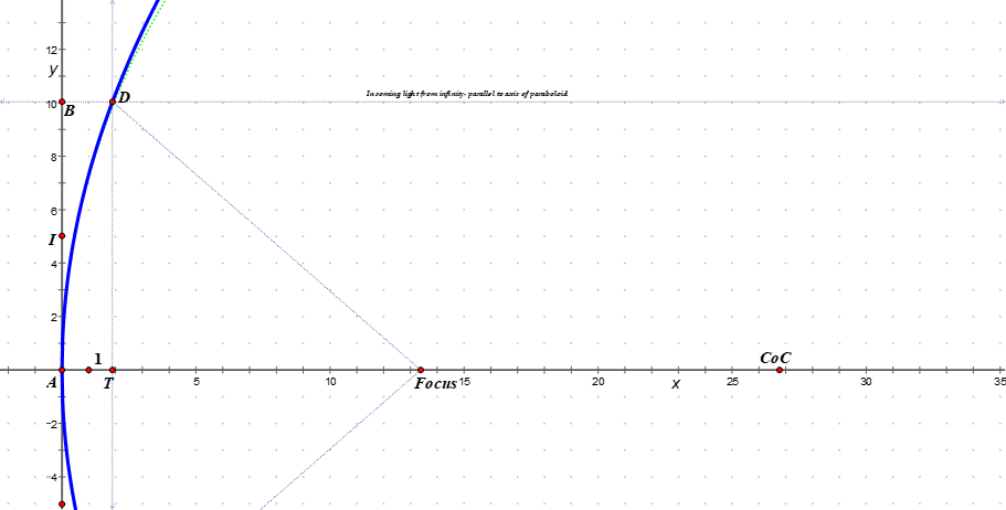
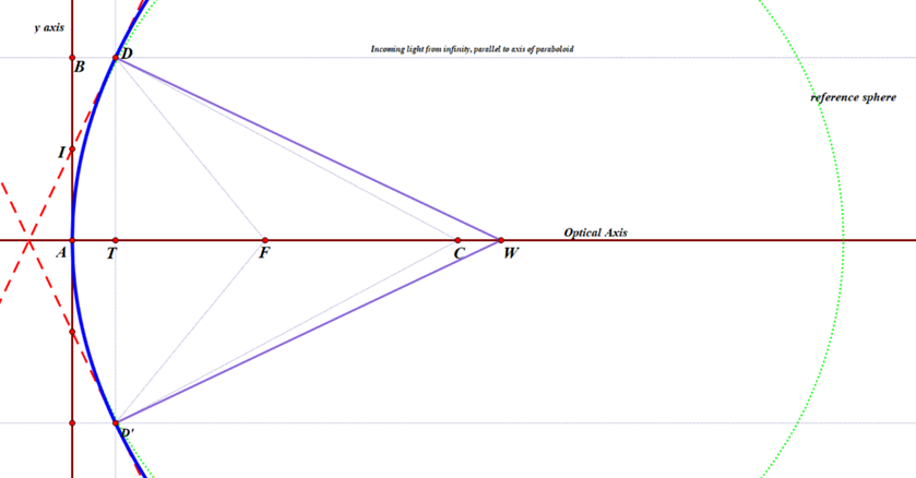
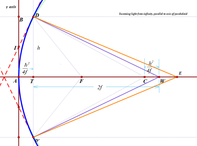
However, 3 dimensions is harder than 2 dimensions, and two dimensions will work just fine for right now. Let us just consider a slice through this paraboloid via the x-y plane, as you see below: a 2-dimensional cross-section of the 3-dimensional paraboloid, sliced through the vertex of the paraboloid, which you recall is at the origin. We can ignore the z values, because they will all be zero, so the equation for the blue parabola is
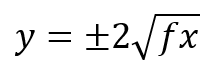
or, if you solve it for y, you get
There is a circle with almost the same curvature as the paraboloid; its center, labeled CoC (for ‘Center of Curvature’) is exactly twice as far from the origin as the focal point. You can just barely see a green dotted curve representing that circle, towards the top of the diagram, just to the right of the blue paraboloid. center of the circle (and sphere). Its radius is 2f, which obviously depends on the location of the Focus.
D is a random point on that parabola, much like point G was earlier, and D’ being precisely on the opposite side of the optical axis. The great thing about parabolic mirrors is that every single incoming light ray coming into the paraboloid that is parallel to the axis will reflect towards the Focus, as we saw earlier. Or else, if you want to make a lamp or searchlight, and you place a light source at the focus, then all of the light that comes from it that bounces off of the mirror will be reflected out in a parallel beam that does not spread out.
In my diagram, you can see a very thin line, parallel to the x-axis, coming in from a distant star (meaning, effectively at infinity), bouncing off the parabola, and then hitting the Focus.
I also drew two red, dashed lines that are tangent to the paraboloid at point D and D’. I am calling the y-coordinate of point D as h (D has y-coordinate -h)and the x-coordinate of either one is
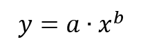
I used basic calculus to work out the slope of the red, dashed tangent line ID. (Quick reminder, if you forgot: in the very first part of most calculus classes, students learn that the derivative, or slope, of any function such as this:
is given by this:
So for the parabola with equation
the slope can be found for any value of x by plugging that value into the equation
Since
the exponent b is one-half. Therefore, the slope is going to be
which simplifies to
Now we need to plug in the x coordinate of point D, namely
we then get that the slope is
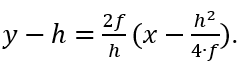
To find the equation of the tangent line, I used the point-slope formula y – y1=m(x – x1). ; plugging in my known values, I got the result
To find where this hits the y-axis, I substituted 0 for x, and got the result that the tangent line hits the y-axis at the point (0, h/2) — which I labeled as I — or one-half of the distance from the vertex (or origin) to the ‘height’ of the zone, or ring, being measured.
Line DW is constructed to be perpendicular to that tangent, so any beam of light coming from W that hits the parabola at point D will be reflected back upon itself. Perpendicular lines have slopes equal to the negative reciprocal of the other. Since the tangent has slope 2f/h, then line DW has slope -h/(2f).
Plugging in the known values into the point-slope formula, the equation for DW is therefore
Here, I am interested in the value of x when y = 0. Substituting, re-arranging, and solving for x, I get
Recall that point C is precisely 2f units from the origin, which means that the perpendicular line DW hits the x axis at a point that is the same distance from the center of curvature CoC as the point D is from the y-axis!
Or, in other words, CW = AT = DE. This means: if you are testing a parabolic mirror with a moving light source at point W, then a beam of light from W that is aimed at point D on the paraboloid will come right back to W, and the longitudinal readings of distance will follow the rule h2/(4f), where h is the radius of the zone, or ring, that you are measuring. Other locations on the mirror which do not lie in that ring will not have that property. This then is the derivation of the formula I was taught over 30 years ago by Jerry Schnall, and found in many books on telescope making – namely that for a moving light source, since R=2f,
where LA means ‘longitudinal aberration and the capital R is the radius of curvature of the mirror, or twice the focal length. So that’s exactly the same as what I computed.
HOWEVER, this formula [ LA=h^2/(2R) ] does not work at all if your light source is fixed at point C, the center of curvature of the green, reference sphere. In the old days, before the invention of LEDs, the light sources were fairly large and rather hot, so it was easier to make them stationary, and the user would move the knife-edge back and forth, but not the light source. The formula I was given for this arrangement by my mentor Jerry Schnall, and which is also given in numerous sources on telescope making was this:
that is, exactly twice as much as for a moving light source. I discovered to my surprise that this is not correct, but it took me a while to figure this out. I originally wrote the following:
But now I can confirm this, thanks in part to two of my very mathematically inclined 8th grade geometry students. Here goes, as corrected:
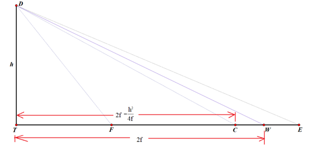
If one is using a fixed light source located at the center of curvature C, and a moving knife-edge, located at point E, the the rays of light that hit the same point D will NOT bounce straight back, because they don’t hit the tangent line at precisely 90 degrees. Instead, the angle of incidence CDW will equal the angle of reflection, namely WDE. I used Geometer’s sketchpad to construct line DE by asking the software to reflect line CD over the line DW.
However, calculating an algebraic expression for the x-coordinate of point E was surprisingly complicated. See if you can follow along!
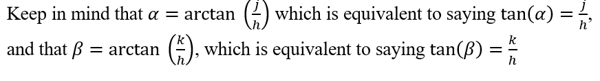
To find the x-coordinate of E, I will employ the tangent of angle TDE.
To make the computations easier, I will draw a couple of simplified diagrams that keep the essentials.
I also tried other approaches, and also got answers that made no sense. It looks like the formula in the 1902 article is correct, but I have not been able to confirm it.
I suspect I made a very stupid and obvious algebra mistake that anybody who has made it through pre-calculus can easily find and point out to me, but I have had no luck in finding it so far. I would love for someone did to point it out to me.
Dear Flat Earthers, Many people have been derogatory of your belief that the Earth is flat. Please note that they are belittling your belief, not you per se. You, personally, are an idiot, but that is probably not your fault.
Here are any number of accessible approaches for discovering the shape of our beloved planet. Enjoy!
* * *
Use Your Phone! On Christmas Day, here in Chicago, I expect there to be snow on the ground because, well, it is winter. On Christmas Day I can pick up my phone and dial up anyone in Australia and ask them “What season is it?” They will tell you that it is summer in Australia. You might want to ask your flat Earth mentors how it could be winter and summer simultaneously on a flat Earth.
Use Your Phone! Go to a globe and pick a spot half way around the Earth (I know it is a false representation in your belief, but humor me.) In the middle of the day, phone somebody at or near that spot. Call a hotel, they are always open. Ask whoever responds “Is it light or dark outside?” They will tell you that it is dark where they are. You might want to ask your flat Earth mentors how it could be light and dark simultaneously on a flat Earth.
Look Up What Local Time Was In the US there was this concept of “local time” which was that “noon” was when the sun was at its highest point in its arc. You could call up people on the telephone who were not that far away and ask them what time it was and they would tell you something different from what your clock was telling you. The farther away they were, the greater the difference would be. On a flat Earth the time would be the same everywhere.
Look Up What Time Zones Are I am writing this in the central time zone in the U.S. These zones were created at the behest of the railroad industry whose dispatchers were going crazy making up schedules for trains when every place had their own times. By creating these “zones” everything would be exactly one hour off from those in neighboring zones, two hours off for the next over zones, and so on. If you don’t believe me . . pick up your phone and dial up a friend who lives a considerable distance (east-west) away from you and ask them what time it is. The time they state will be a whole number of hours away from your time. Heck, even the NFL knows this. When I lived on the left coast, the games started at 10 AM and 1 PM. Now that I live in the central time zone, the games start at 12 Noon and 3 PM. Over New York way the games start at 1PM and 4 PM. Do you think those games are replayed in one hour increments? Nope, time zones!. You might want to ask your flat earth mentors how it could be that simultaneous games start at different times on a flat Earth.
Watch the Video Astronauts in the International Space Station (ISS) have made continuous videos of an entire orbit of the Earth. It takes only about an hour and a half about the length of a typical Hollywood movie. During the whole movie the earth appears round, and yet it is clear that different continents are passing in our view.
Now you may argue that NASA made this movie as propaganda for the Round Earth Conspiracy. It is certainly within our CGI abilities at this point, but you may want to ask why NASA would want to do such a thing? Plus, many astronauts have taken their own cameras aboard and taken pictures for themselves and they show the same thing. How could the Round Earth Conspiracy have allowed that to happen? It must be incompetence! Conspiracies aren’t what they used to be!
Da Balloon, Boss, Da Balloon Many amateurs, unaffiliated with the government, have launched rockets and balloons high up into the atmosphere to take pictures. Every damned one of those pictures shows that the Earth is round. How come all of those cameras ended up pointed at the curved edge of your round and flat disk Earth? Such a coincidence!
An Oldie But Goodie #1 Occasionally, during a lunar eclipse, you can see the shadow of the earth falling upon the Moon. The shadow is always circular. This would be true if the flat earth were always dead on to the Moon, but the Moon orbits the Earth and wouldn’t a flat Earth be edgewise, often as not, and wouldn’t that create a non-round shadow on the Moon? Inquiring minds want to know.
An Oldie But Goodie #2 It was claimed that one of the first demonstrations of the earth being round was the observation of ships sailing west from Europe/England could be observed for a while but the ship itself was lost to sight while the mast was still visible. This would not happen on a flat Earth. The whole ship would just get smaller and smaller as it sailed west.
For pity’s sake, I live 22 stories up and the shores of Lake Michigan and I cannot see anything directly opposite me in Michigan. All I can see is water, with any kind of magnification I can muster. And I am not looking across the widest part of this lake! If the earth were flat, the lake would be flat and I could see the Michigan shore.
And Finally . . .
All of the fricking satellites! Do the math. What kind of orbit is stable around a flat disk earth? Answer none! And there are hundreds of the danged things in orbit.
Also, just for giggles. Look up what a Foucault pendulum is, And explain its behavior based upon a flat Earth.
PS You may be getting good vibes in your special knowledge that you know something other people do not. However, would not that special feeling be more worthwhile were you to volunteer at a food bank or a day care center or senior center? Wouldn’t doing something worthwhile be more rewarding that making a statement about how those pointy-headed intellectuals aren’t so smart?
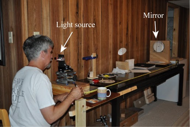
PPS I have seen the cute models with the Sun and Moon on sticks rotating around (see photo above). If that were the case, everyone could see the Sun and Moon all day, every day. (There is straight line access to both objects in that model from everywhere on the flat disk.) Do you see the Sun and Moon all day, every day? No? Maybe someone who had more creativity than knowledge came up with those models. They do sell well, I must admit, so maybe their interest is commercial.
PPPS Regarding the 200 foot wall of ice that supposedly exists at the “edge of the disk,” supposedly so all the water doesn’t flow off and be lost into space. By now don’t you think someone would have sailed next to that wall all of the way? That distance would be somewhere in the neighborhood of a 28,000 mile trip. Has anyone ever report such a thing? Hmm, I wonder why not
The other regulars and I at the DC ATM group at the CCCC have been trying to test a 12 inch Cassegrain mirror and telescope manufactured nearly 50 years ago by a company called Ealing and currently owned by the Hopewell Observatory, of which I am a member. It hasn’t been easy. I discussed this earlier on Cloudy Nights.
Reports from several people, including Gary Hand and the late Bob Bolster, indicated that the optics on this mirror weren’t good at all. Apparently the folks at the University of Maryland’s observatory were sufficiently unhappy with it that they either sold it or gave it to National Capital Astronomers, a local astronomy club, who in turn gave it or sold it to Hopewell Observatory.
With a plain-vanilla Ronchi test, we could see that the mirror was very smooth and continuous, with no turned edge, astigmatism, or bad zones. With the Foucault/Couder zonal test (aka “Foucault” test) , I got results indicating that it was seriously overcorrected: some sort of hyperboloid, rather than the standard paraboloid characteristic of classical Cassegrain telescopes, which have a parabolic primary mirror and a hyperbolic secondary mirror.
However, I have begun losing my faith in my zonal readings, because they often seem to give results that are way out of whack compared to other testing methods.
So we decided to do some additional tests: the Double-Pass Auto-Collimation (DPACT) test used by Dick Parker, as well as the Matching Ronchi test (MRT).
The DPACT is very fiddly and exacting in its setup. We used (and modified) the setup lent to us by Jim Crowley and illustrated by him at his Astro Bananas website. Our results seem to show that the mirror is in fact NOT parabolic, rather, overcorrected, which confirms my Foucault measurements. If it were a perfect paraboloid, then the ronchi lines would be perfectly straight, but they definitely are NOT: they curve one way when inside the focal point, and curve the other when the tester is outside the focal point.
We also tested the entire setup on a radio tower that was about half a mile (~1km) distant. We found that the images were somewhat blurry no matter what we did.
We also attempted the MRT on the same mirror. However, requires very accurate photography and cutting-and-pasting skills in some sort of graphics programs. What you are inspecting is the curvature of the Ronchi lines. Here is the result that Alan T and I got last night:
In black is the ideal ronchigram for this mirror, according to Mel Bartels’ website. The colored picture is the one we made with either my cell phone or the device I finished making earlier this week, shown in my previous post. Here are the two images, separated rather than superimposed:
The mirror’s focal length is 47.5″ and the grating has 100 lines per inch, shown somewhat outside of the radius of curvature. The little ‘eyelash’ on the lower left is simply a stray wire that was in the way, and doesn’t affect the image at all. The big hole in the middle is there because the mirror is a cassegrain.
I don’t know about you, but I don’t really see any differences between the real mirror and the theoretical mirror. Do you?
Conclusion
So, what does this all mean?
One possibility is that the mirror is in fact perfectly parabolic (as apparently shown by the MRT, but contrary to what I found with Foucault and DPACT) but there is something wrong with the convex, hyperbolic secondary.
Another possibility is that the mirror is in fact NOT parabolic, but hyperbolic, as shown by both my Foucault measurements and the DPACT (and contrary to the MRT), which would mean that this telescope was in fact closer to a Ritchey-Chretien; however, since it was marketed as a classical Cassegrain, then the (supposedly) hyperbolic secondary was in fact not tuned correctly to the primary.
The answer is left as an exercise for the reader.
A star test would be the best answer, but that would require being able to see a star. That hasn’t happened in these parts for quite some time. In addition, it would require an eyepiece holder and a mount of some sort. Or else setting up an indoor star…
Here is the latest incarnation of my webcam Ronchi and knife edge (or Foucault) tester. It’s taken quite a few iterations to get here, including removing all the unnecessary parts of the webcam. I attach a still photo and a short video. The setup does quite a nice job of allowing everybody to see what is happening. The only problem is setting the gain, focus, exposure, brightness, color balance, contrast, and so on in such a way that what you see on the screen resembles in any way what your eye can see quite easily.
We at the Hopewell Observatory have had a classical 12″ Cassegrain optical tube and optics that were manufactured about 50 years ago.; They were originally mounted on an Ealing mount for the University of Maryland, but UMd at some point discarded it, and the whole setup eventually made its way to us (long before my time with the observatory).
The optics were seen by my predecessors as being very disappointing. At one point, a cardboard mask was made to reduce the optics to about a 10″ diameter, but that apparently didn’t help much. The OTA was replaced with an orange-tube Celestron 14″ Schmidt-Cassegrain telescope on the same extremely-beefy Ealing mount, and it all works reasonably well.
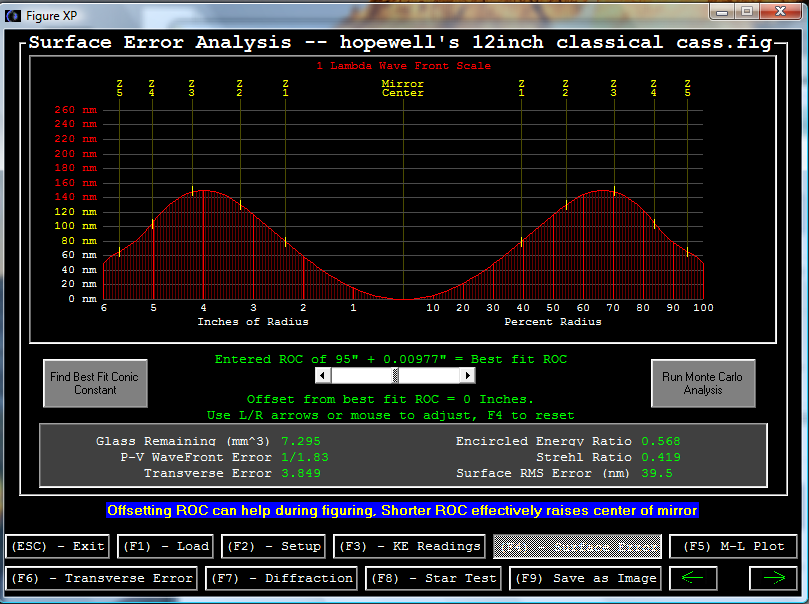
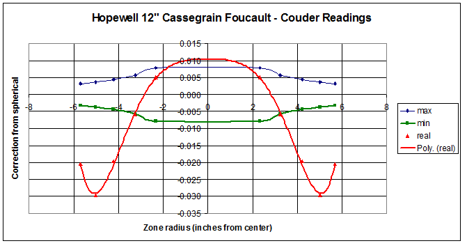
Recently, I was asked to check out the optics on this original classical Cassegrain telescope, which is supposed to have a parabolic primary and a hyperbolic secondary. I did Ronchi testing, Couder-Foucault zonal testing, and double-pass autocollimation testing, and I found that the primary is way over-corrected, veering into hyperbolic territory. In fact, Figure XP claims that the conic section of best fit has a Schwartzschild constant of about -1.1, but if it is supposed to be parabolic, then it has a wavefront error of about 5/9, which is not good at all.
Here are the results of the testing, if you care to look. The first graph was produced by a program called FigureXP from my six sets of readings:
I have not yet tested the secondary or been successful at running a test of the whole telescope with an artificial star. For the indoor star test, it appears that it only comes to a focus maybe a meter or two behind the primary! Unfortunately, the Chevy Chase Community Center where we have our workshop closes up tight by 10 pm on weekdays and the staff starts reminding us of that at about 9:15 pm. Setting up the entire indoor star-testing rig, which involves both red and green lasers bouncing off known optical flat mirrors seven times across a 60-foot-long room in order to get sufficient separation for a valid star test, and moving two very heavy tables into said room, and then putting it all away when we are done, because all sorts of other activities take place in that room. So we ran out of time on Tuesday the 5th.
A couple of people (including Michael Chesnes and Dave Groski) have suggested that this might not be a ‘classical Cassegrain’ – which is a telescope that has a concave, parabolic primary mirror and a convex, hyperbolic secondary. Instead, it might be intended to be a Ritchey-Chretien, which has both mirrors hyperbolic. We have not tried removing the secondary yet, and testing it involves finding a known spherical mirror and cutting a hole in its center, and aligning both mirrors so that the hyperboloid and the sphere have the exact same center. (You may recall that hyperboloids have two focal points, much like ellipses do.)
Here is a diagram and explanation of that test, by Vladimir Sacek at http://www.telescope-optics.net/hindle_sphere_test.htm
FIGURE 56: The Hindle sphere test setup: light source is at the far focus (FF) of the convex surface of the radius of curvature RC and eccentricityε, and Hindle sphere center of curvature coincides with its near focus (NF). Far focus is at a distance A=RC/(1-ε) from convex surface, and the radius of curvature (RS) of the Hindle sphere is a sum of the mirror separation and near focus (NF) distance (absolute values), with the latter given by B=RC/(1+ε). Thus, the mirrorseparation equals RS-B. The only requirement for the sphere radius of curvature RS is to be sufficiently smaller than the sum of near and far focus distance to make the final focus accessible. Needed minimum sphere diameter is larger than the effective test surface diameter by a factor of RS/B. Clearly, Hindle test is limited to surfaces with usable far focus, which eliminates sphere (ε=0, near and far focus coinciding), prolate ellipsoids (1>ε>0, near and far foci on the same, concave side of the surface), paraboloid (ε=1, far focus at infinity) and hyperboloids close enough to a paraboloid to result in an impractically distant far focus.
We discovered that the telescope had a very interesting DC motor – cum – potentiometer assembly to help in moving the secondary mirror in and out, for focusing and such. We know that it’s a 12-volt DC motor, but have not yet had luck tracking down any specifications on that motor from the company that is the legatee of the original manufacturer.
I help run the amateur telescope-making workshop at the Chevy Chase Community Center in Washington, DC, sponsored and under the auspices of the National Capital Astronomers. Both the NCA and its ATM group have been on-going since the 1930’s, well before I was born. In our ATM group, have the somewhat esoteric thrill of manufacturing incredibly accurate scientific devices (telescopes), from scratch, with not much more than our bare hands and a few tools. And then we go and use them to observe the incredible universe we come from.
Since these telescope mirrors are required to be insanely accurate, we need extremely high-precision ways of testing them. However, we don’t have the tens or hundreds of thousands of dollars needed to purchase something like a professional Zygo Interferometer, so we use much cheaper ways of testing our mirror surfaces.
Some of those methods are associated with the names Foucault, Couder, Bath, Ronchi, Ross, Everest, and Mobsby, or are described with words like “knife-edge”, “double-pass” and “wire”. They all require some relatively simple apparatus and skill and practice in measurement and observation.
We are of the opinion that no one single test should be trusted: it’s easy to make some sort of error. (I’ve made plenty.) You may perhaps recall the disaster that happened when the Hubble Space Telescope mirror passed one test with flying colors, and other tests that weren’t so good were ignored. When the HST finally flew in orbit, it was discovered that the mirror was seriously messed up: the test that was trusted was flawed, so the mirror was also flawed.
We don’t want to do that. So, at a minimum, we do the Ronchi and Foucault/Couder knife-edge tests before we say that a mirror is ready to coat.
But the ultimate test of an entire telescope is the star test.
In principle, all you need for that is a steady star, your telescope, a short-focal-length eyepiece, and a copy of Richard Suiter’s book on star-testing optical telescopes.
Unfortunately, around here, it’s often cloudy at night, and if it’s clear, it might be windy, and around the CCCC building there are lots of lights — all of which make star-testing a scope on the two evenings a week that we are open, virtually impossible. We aren’t open in the daytime, and even if we were, I don’t see any ceramic insulators on any telephone poles that are both small enough and far enough away to use as artificial stars in the manner that Suiter describes. (There are a few radio towers visible, but I doubt that their owners would let us climb up one of them and hang up a Christmas tree ornament near the top!)
I’ve been reading a few websites written by folks who have done just that, and it seems to be a bit easier than I thought. The key is to get a source of light that acts like a star at astronomical distances — but close enough that we can fit it inside the basement of the CCCC, probably not in the woodshop where we make the scopes, but more likely out in the hallway or in the large activity room next door, both of which are about 40 or 50 feet long.
So here are my preliminary calculations.
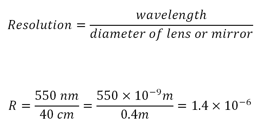
First off, it appears that the resolving power of a telescope equals the wavelength being used, divided by the diameter of the objective lens or mirror, both expressed in the same units. The result is in radians, which you can then turn into degrees, arc-minutes, arc-seconds, or whatever you like, but it’s perhaps easier to leave in radians. In any case, the larger the diameter, the tinier the angle that your telescope can resolve if it’s working properly.
I am going to use a 16-inch mirror diameter, or about 0.4 meters, as an example, and I will use green light at about 560 nanometers (560 x 10^-9 m) because that’s pretty close to the green mercury line we have in our monochromatic light box. I then get that the resolution is 1.4×10^-6 radians.
(We can convert that into arc-seconds by multiply that by 180 degrees per PI radians and by 60 arc-minutes per degree and by 60 arc-seconds per arc-minute; we then get about 0.289 arc-seconds. If we were to use an 8-inch mirror, the resolution would be half as good, meaning the object would need to be twice as big to be resolved, or about 0.578 arc-seconds.)
I read that one can make an artificial star by using an ordinary eyepiece and a small illuminated hole that is put some distance away from the eyepiece. The entire setup is aimed at the telescope, and then you have an artificial star. Here is the general idea:
Supposedly, the equations go as follows, with all of the dimensions in the same units. I think I will use millimeters.
We want to make it so that the size of the artificial star will be small enough to be below the limit of resolution of any telescope we are making. I am pretty sure that we can set things up so that there is 40 feet (13 meters) between our telescope rig and the table or tripod on which we sill set up this artificial star.
I also know that I can find an eyepiece with a focal length of 12 mm that I’m willing to use for this purpose, and I also purchased some tiny little holes from “Hubble Optics” that are of the following sizes: 50, 100, 150, 200, and 250 microns, or millionths of a meter. Those holes are TINY!!! So that takes care of H and F. I still need to figure out what SS should be.
A few lines ago, I found that for a 16-inch telescope, I need a resolution of about 1.4×10^-6 radians. The nice thing about radians is that if you want to find the length of the arc at a certain radius, you don’t need to do any conversions at all: the length of the arc is simply the angle (expressed in radians) times the length of the radius, as shown here:
So if our artificial star is going to be 13 meters away, and we know that the largest angle allowed is roughly 1.4×10^-6 radians, I just multiply and I get 1.82×10^-5 meters, or 1.82 x 10^-2 millimeters, or 18.2 microns.
Which means that I already have holes that are NOT small enough: the 150-micron holes are about 10 times too big at a distance of 13 meters, so my premature rejoicing of a few minutes ago, was, in fact, wrong. So, when I make the artificial star gizmo, I’ll need to figure out how to make the ‘star size’ to be roughly one-tenth the size of the holes in the Hubble Optics micro-hole flashlight.
Or, if I rearrange the equation with the L, H, F and SS, I get that L = H * F / SS. The only unknown is L, the distance between the hole and the eyepiece/lens. For H, I have several choices (50, 100, 150, 200 and 250 microns), SS is now known to be 18 microns or so (36 if I want to test an 8-incher), and I plan on using a 12.5 mm eyepiece. If I plug in the 150 micron hole, then I get that L needs to be about 104 millimeters, or only about 4 inches. Note that the longer L is, the smaller the artificial star becomes. Also, if I replace the 12.5 mm eyepiece with a shorter one, then the artificial star will become smaller; similarly, the smaller the Hubble Optics hole, the smaller the artificial star. This all sounds quite doable indeed.
A. Polishing pads do a great job of polishing out the pits, but they tend to leave a rough surface that is not a true paraboloid or even a section of a sphere, unless you are very, very lucky. Most folks will switch to a pitch lap for the figuring process, which involves removing sub-microscopic amounts of glass from various zones on your mirror, in order first to make it into a section of a sphere, and then into the bottom of a paraboloid – the only geometric figure that will reflect all of the rays that come from distant stars onto a single focal point. Many treatises have been written about figuring, and I’m not going to add to that list. “Understanding Foucault” by David Harbour gives an excellent explanation of the figuring process, as does Mel Bartels here. However, here are some of the basics:
B. You will need a pitch lap, made either of Gugolz or Acculap or Tempered Burgundy pitch. The first two are synthetic products whose composition is probably secret; the third one is made from the sap of coniferous trees. I’m not going to describe the process of making a pitch lap here, but I combine some of the methods of Carl Zambuto and John Dobson when I make a new one; you can watch it as we do it for you. It’s much less work if you can use a pitch lap that was made by or for someone else who has finished their own project. Sometimes a previously-used pitch lap will have sat around too long and might need to be scraped off and remelted. We generally use roughly square facets, which allow the pitch to flow better and conform itself to your mirror. Without the facets, any high points on the lap have a hard time being lowered. We also tend to use netting or a single-edge razor blade to make minifacets, which further help the lap to conform to the mirror.
C. Pitch is weird stuff. When it’s warm, it flows and it’s very sticky. When it’s cold, it is fairly hard, and you can shatter it with a hammer. If you leave a pencil or a coin on a pitch lap overnight, the next day you can see all of the details of the pencil or coin reproduced perfectly in the pitch. We want the lap to conform itself to your mirror. Then we use the pitch lap to remove all of the irregularities that were left by the polishing pads. So, we warm up the pitch lap to soften it a bit (using a heat lamp or hot water), spread Cerox or rouge onto your mirror, and then press the two together briefly but firmly. We often use some netting to create micro-facets, which help the pitch conform to your mirror even more.
D. The figuring stage can severely try your patience, especially if the tests show a surface that looks weird. But relax! If you persevere and don’t drop the mirror on the ground, success is guaranteed, since it’s just a matter of removing the correct millionth of an inch or two (much less than a micrometer) of glass from the correct zonal ring to achieve near-perfection. One needs to make sure that the lap actually conforms to the mirror; bad contact between the two can cause trouble, and so can a pitch lap that is too hard, too soft, or too thin. All of those are fairly easily fixed, with remarkable results. And we are here to help.
E. One major problem that can affect mirrors is a Turned-Down Edge (TDE). Opinions vary on what causes this dreaded condition, but the evidence suggests to me that TDE appears when the lap is exactly the same size, or slightly smaller, than the mirror itself. To avoid a TDE, do not chip off the parts of the pitch lap that ‘mushroom’ out past the edge. Let them stay there.
F. You will be instructed in a specific set of strokes which will first make your mirror into a sphere. Then, you will be instructed in a different set of strokes that will make your mirror into a good approximation of a perfect paraboloid. Texereau, LeCleire, and many other books describe those strokes. So did Leon Foucault in his 1859 article, which you can find on this blog/website. In our workshop, we will test your mirror frequently with a combination of tests, many of them invented by Foucault but later modified.
G. A very fast qualitative test is the Ronchi test, which you can look up. It gives you almost instant feedback on the presence or absence of bad features like turned-down edge (TDE), zonal defects (high or low rings), astigmatism (lack of symmetry), roughness, and so on. It will tell you whether your mirror is a sphere or not – if the Ronchi lines are perfectly straight, then you have a sphere. If they are not straight, then the test can tell us if your mirror is on the way towards being an ellipsoid with the long axis perpendicular to the mirror (or parallel to it), or a hyperboloid, or your goal, a paraboloid. There are several computer programs that provide simulations of what a perfect mirror should look like under the Ronchi test, but I’ve found you can’t always trust those simulations. RonWin is one such program, and Mel Bartels has another on one of his web pages.
H. A more time-consuming test that I find is necessary is the Foucault test as modified by Andre Couder, also known as the numerical knife-edge test with zones. If the Ronchigram looks good, and the numbers in the knife-edge zonal test are also within acceptable limits, then the mirror is done. A slight modification of this test is known as the Wire Test, which works well on fast mirrors. David Harbour’s article does an excellent job of explaining this test. One can use a pinstick method for marking the zones, or one could write directly on the mirror with a Sharpie, but we use a version that uses cardboard masks with holes cut out at carefully-measured zones.
I. We have tried a number of other tests, such as the double-pass autocollimation test, the Mobsby Null test, and the Bath Interferometer test, and have had difficulties getting good results with them. Therefore, we are continuing to use the Ronchi and Knife-Edge Zonal tests.
J. However, the best test of any mirror is the Star Test, which is the subject of an entire book by Richard Suiter. Some do this in the daylight, using sunlight reflected from very distant insulators on electrical poles. Most do it at night, but it requires steady air (‘good seeing’) and a clear sky as well. The Star Test is much easier to perform if the mirror is already aluminized and in a working telescope, which brings us to….